Adjustable Voltage Regulator Project
Learn how to make an adjustable voltage regulator using LM317 or LM338. Perfect for DIY electronics projects requiring a variable DC output voltage.

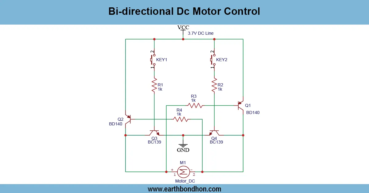
Simple variable voltage circuit
A Voltage adjustable circuit is one of the easiest and effective methods of regulating the output voltage of a power supply. It is common in electronic laboratories and Do-It-Yourself projects as a means of providing power to other devices that need a different amount of voltage. The circuit schematic is usually constructed with an LM317 adjustable regulator so the output can vary anywhere between 1.25V to up to 30V, depending on what input and resistor combinations are hooked up.
variable voltage diy kit Formula:
- Output Voltage: Vout = 1.25 × (1 + R2/R1) + Iadj × R2
- R1: Typically 240Ω
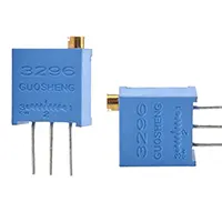
- R2: Adjustable resistor or potentiometer
- Input Voltage: Minimum 3V higher than desired output
- Capacitors: Cin = 0.1µF, Cout = 1µF or more
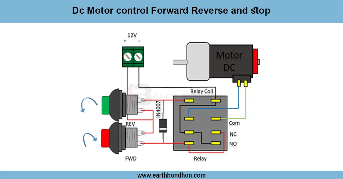
adjustable voltage regulator project
A voltage adjustable circuit is made to adjust the output voltages over a range best suited for testing, prototyping, and a variable power supply. The components that are incorporated in this project generally include variable resistors (potentiometers), LM317 or LM338 regulators, capacitors, and heat sinks so that adjustable results can be handled in a reliable and efficient manner. The users can adjust resistance in the circuit by rotating the potentiometer and affecting the output voltage. It has many applications in self-construct projects, charging batteries, and power management customized set-ups.
diy variable power supply
| R1 (Ω) | R2 (Ω) | Output Voltage (V) |
|---|---|---|
| 240 | 470 | 3.7 |
| 240 | 1000 | 6.5 |
| 240 | 1800 | 10.6 |