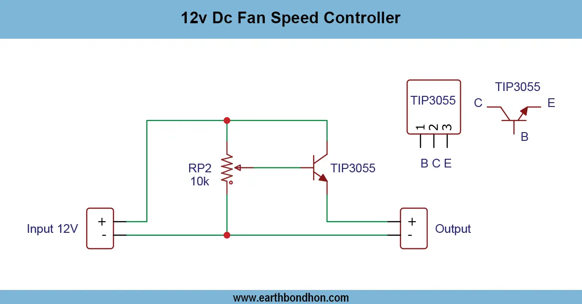


12v DC Fan Speed Controller
Control DC motor speed using TIP41 transistor. Simple PWM-based circuit allows smooth speed adjustment for small DC motors in robotics and DIY projects.

DC motor PWM control TIP41
A DC motor speed controller featuring TIP41 permits a DC motor to be controlled in speed with ease through the application of PWM. It works well in small DC motors in robotics, hobby, and automation systems.
adjustable motor speed transistor
The TIP41-based DC Motor Speed Controller is an easy and inexpensive means of controlling speed in a DC motor. TIP41 is an NPN power transistor that can work with low to medium-current motors. It operates by employing the PWM (Pulse Width Modulation) to regulate the average voltage supplied to the motor. The TIP41 transistor can be driven by a microcontroller, a 555 timer IC, or a PWM generator using a potentiometer. The motor speed can be changed in a smooth manner by changing the duty cycle. The system suits small robotics, hobby, conveyor systems, or automated systems. The spike of voltages on the inductive load on the transistor is advised to be mitigated by flyback diodes across the motor. Continuous operation of TIP41 may also require a heat sink.
Work / Installation (Inputs → Outputs)
- Power Input → DC supply voltage suitable for motor.
- TIP41 Transistor → Switches motor current according to PWM signal.
- PWM Control → Adjusts transistor conduction to vary motor speed.
- Flyback Diode → Protects TIP41 from inductive spikes.
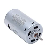
- Output → Motor rotates at adjustable speed.
- Installation → Assemble on PCB or perfboard; use a heat sink if needed; connect the PWM input to the transistor base via a resistor.
Testing & Final Adjustments
Connect the motor and power supply after getting assembled. Stepwise apply PWM input and observe motor response in speed. Note that overheating of the TIP41 transistor can be avoided with a heatsink. Ensure that the flyback diode is well-connected to ensure that the transistor is not damaged by voltage spikes. Test of the various PWM duty cycles to provide good acceleration and deceleration. Ensure that the motor is reliable when it is running under different loads. Adjust the base resistor or the PWM source to the optimum. When verified, the circuit offers stable, cost-effective, and efficient DC motor speed control that can be used in robotics or in DIY applications.
Frequently Asked Questions - 12v DC Fan Speed Controller:
Can TIP41 control motor speed?
Yes, using PWM signals to adjust current flow to the motor.
Is it suitable for small motors?
Yes, TIP41 handles low to medium current DC motors.
Do I need a flyback diode?
Yes, to protect TIP41 from voltage spikes.
Can it handle high current?
Limited to TIP41 ratings; use heat sink if necessary.
Is PWM required?
Yes, PWM allows smooth speed control.
Can it be used in robotics?
Yes, ideal for small robotics projects.
Do I need a heat sink?
Recommended for continuous operation.
Is it beginner-friendly?
Yes, simple transistor-based design.
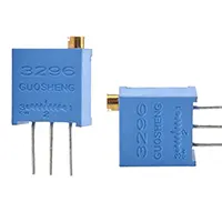
Can I adjust speed with a potentiometer?
Yes, by connecting it to the PWM circuit.
Is it cost-effective?
Yes, uses readily available TIP41 and simple components.