Creators
Earth Bondhon Author
Earth Bondhon
CalculatorToolsProjectExpert
Reviewers
Małgorzata Koperska, MD Steven Wooding
Last updated: January 14, 2026

3.7V Battery Level Indicator Circuit Using LEDs

🇺🇸
English
Default
🇪🇸
Español
Spanish
🇫🇷
Français
French
🇩🇪
Deutsch
German

Components List

BC547 Transistor

BC547 Transistor

General-purpose NPN bipolar junction transistor (BJT)

1N4007 Diode

1N4007 Diode

General-purpose 1000V, 1A diode

220-ohm Fixed Resistor 1/4W

220R Fixed Resistor 1/4W

A 220-ohm resistor rated for 0.25 watts

1K Fixed Resistor 1/4W

1K Fixed Resistor 1/4W

A 10,000-ohm resistor rated for 0.25 watts

3V LED 5mm

3V LED 5mm

3V, 5mm round light-emitting diode

*Please note: These are affiliate links. I may make a commission if you buy the components through these links. I would appreciate your support in this way!

3.7v battery level indicator circuit

A simple 3.7V battery level indicator circuit using LEDs to monitor charge status for lithium-ion batteries. Ideal for DIY electronics and portable devices.

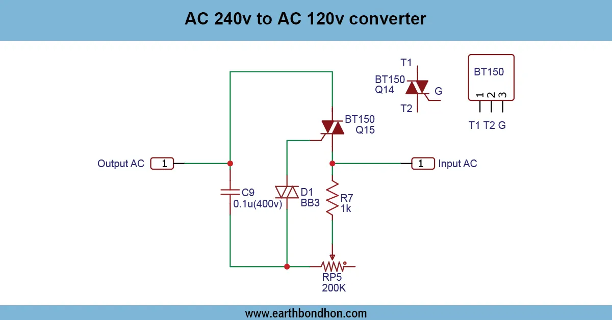
3.7v battery indicator diagram

A 3.7V battery level indicator circuit shows the real-time voltage of a lithium-ion battery. It has LEDs to indicate the status of the battery (full, medium, or low). It is a circuit that prevents deep discharge of the battery and makes devices that are battery-powered perform more efficiently. Easy to construct using a small number of resistors and a comparator or a zener diode, it is suited to embedded applications and devices that run on batteries.

High-quality LED emergency light circuit

The emergency light incorporates an LED-powered rechargeable battery, which is usually 12V or 6V. They are automatic charging and switching circuits that make sure that the battery will always be fully charged, and lights will automatically turn on when there is a power cut. With this circuit, electronics enthusiasts can design an effective and affordable emergency lighting system and also gain some useful philosophy of circuit design.

Key Features and Advantages

  • Automatic switching from mains to battery
  • Energy-efficient LED illumination
  • Long-lasting rechargeable battery
  • Overcharge and short-circuit protection
  • Compact and easy-to-assemble design

Components Required for Emergency Light Circuit

  • Rechargeable battery (12V/7Ah or suitable)
  • LEDs or high-brightness LED strips
  • Diode (e.g., 1N4007 for protection)
  • Resistors for current limiting
  • Transistor or MOSFET for switching (e.g., BC547)
  • Voltage regulator IC (optional)
  • Battery charging IC or charging circuit
  • Switches and connectors
  • PCB or breadboard
  • Wires, heat shrink, soldering tools

Working Principle

Battery Charging Circuit

When mains power is available, the charging circuit keeps the battery fully charged. The charging current is regulated to prevent battery overcharging or damage.

Automatic Light Control

A transistor or MOSFET senses the presence of mains power. When mains supply fails, it switches on the LED lights automatically.

LED Driver Section

Current-limiting resistors or voltage regulators ensure proper LED brightness and prevent damage due to excess current.

Overcharge and Short-Circuit Protection

A diode prevents reverse current flow from the battery. Fuses or current limiters protect against short circuits.

Circuit Diagram of High-Quality Emergency Light

  • Connect the rechargeable battery to the charging circuit.
  • Add a diode in series to prevent reverse current.
  • Integrate a transistor or MOSFET for auto-switching.
  • Connect LEDs with appropriate resistors or a regulator.
  • Add an optional fuse for protection.
  • Test operation with mains ON and OFF.

Step-by-Step Construction Guide

  1. Assemble the battery charging circuit on PCB.
  2. Connect the battery and test charging voltage.
  3. Wire LED section with resistors.
  4. Install transistor/MOSFET for auto-switching.
  5. Mount components safely on a board or enclosed box.
  6. Test charging and emergency lighting functions.
  7. Adjust brightness using resistors or regulator.

Applications of Rechargeable Emergency Light

  • Home lighting during power outages
  • Office emergency illumination
  • Workshops or industrial areas
  • Portable emergency lamps
  • DIY learning projects

Safety Precautions

  • Avoid overcharging battery
  • Use insulated wires and secure terminals
  • Do not short battery terminals
  • Use heatsinks if transistor/MOSFET heats up
  • Test before final installation

Troubleshooting Common Issues

LEDs Not Lighting

  • Check battery voltage and wiring
  • Verify transistor/MOSFET switching

Battery Not Charging

  • Check diode orientation
  • Ensure correct mains voltage

Overheating or Flickering

  • Check current-limiting resistors
  • Verify LED connections and transistor rating

Frequently Asked Questions - 3.7v battery level indicator circuit:

What is a 3.7V battery level indicator circuit?

It's a circuit that shows the voltage status of a 3.7V battery using LEDs.

Can I use this for lithium-ion batteries?

Yes, it’s designed for standard 3.7V lithium-ion or LiPo cells.

How many LEDs are needed?

Typically 3 to 5 LEDs represent different charge levels.

What components are required?

Resistors, LEDs, zener diodes or op-amps, and a 3.7V battery.

Is this circuit accurate?

For general indication, yes; for precision, use a microcontroller-based monitor.

Does it drain battery power?

Minimal power is consumed when LEDs light up.

Can it show full and low charge levels?

Yes, it shows full, medium, and low voltage levels using LED colors.

Can I adjust voltage levels?

Yes, by tuning resistor values or using voltage dividers.

Can I integrate this into a portable device?

Yes, it’s compact and ideal for embedded electronics.

How do I test the circuit?

Connect a variable power supply or battery and monitor LED behavior.

Comments

Please login to comment.

Earth Bondhon

Earth Bondhon

Calculator Tools Project

Md. Jony Islam is a highly skilled professional with expertise in electronics, electrical, mechanical, and civil engineering, as well as finance. Specializing intransformer service and maintenance for 33/11kV substations, he ensures reliable and efficient electrical systems. His mechanical engineering skills drive innovative designs, while his financial acumen supports effective project budgeting. With a strong foundation in civil engineering, he contributes to robust infrastructure development. Md. Jony Islam's multidisciplinary approach ensures efficiency, quality, and reliability across all projects.