Adjustable Power Supply IGBT
Build an adjustable power supply using an IGBT with step-by-step circuit, installation guide, testing, and safe operation tips for beginners and professionals.

Adjustable power supply igbt:
A variable power supply with an IGBT provides a feasible method of controlling voltage and current in high power. In comparison to conventional regulators, the IGBTs are more efficient, faster in switching, and have better thermal performance. With a PWM controller, including a potentiometer, the output voltage is smooth between input and output, and is therefore applicable in DIY electronics, labs, and power systems.
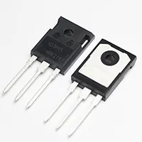
High current power supply igbt:
A variable power supply with an IGBT (Insulated Gate Bipolar Transistor) will be developed to work with high current and voltage. This is an effort to combine a rectifier, filter, and PWM-controlled IGBT stage to generate a smooth and adjustable DC voltage. The AC input is reduced, rectified, filtered, and regulated by the IGBT with the help of PWM signals. The duty cycle is adjusted by a potentiometer such that the output voltage is adjustable to various loads. The circuit has safety, efficiency, and is suitable for high-power applications such as DC motors, inverters, and charging. The equipment is installed well, cooled, and has protective features, which guarantee high levels of reliability in the long run.
⚡ Work & Installation (Input → Output):
The circuit begins with AC mains and a transformer, which reduces the voltage. This is corrected by a bridge rectifier and evened out with filter capacitors. The PWM-driven IGBT switching stage is used to vary the duty cycle to control the voltage. This output is fed through an LC filter and produces clean, adjustable DC. Output voltage is adjusted by potentiometer settings, and snubber diodes, fuses, and cooling are used to make sure that it operates safely.
Testing & Final Adjustments:
Ensure the correct connection of all the wiring connections before turning the power on, and that the rectifier and filter capacitors are aligned correctly. Turn the circuit on with a variac or a current-limited supply to prevent the sudden bursts. Measure the input and output using a multimeter. Adjust the potentiometer gradually to verify the voltage variation at the output. Make sure the PWM frequency is stable (more than 20kHz in order to minimize noise). Real load performance can be checked by connecting a dummy load, such as a power resistor or a small DC motor. Measure IGBT temperature at the operating point; excessive heatsinking can be reduced by heatsinking or by adding a cooling fan. Make sure that the fuse and snubber circuits are working. Once your desired load has been tested successfully, then connect your desired load and again test your voltage stability throughout the working range. The last calibration ensures stable long-term functioning.