Simple Dimmer Light Circuit
Learn to build a Simple Dimmer Light Circuit to adjust light brightness. Step-by-step DIY guide with components, working principle, and circuit diagram included.

What is a Simple Dimmer Light Circuit?
Simple Dimmer Light. This is an easy project made for controlling the intensity of Lamps or simply turning the lights on and off. It is achieved by changing the voltage or pulse width that gets sent to the light, and as a result, there is no flicker in most cases. For AC lamps, TRIACs or SCRs are used in general, and for DC ones, MOSFETs driven by a PWM can easily dim the light.
DIY dimmer light circuit
Simple Dimmer Light Circuit Simple dimmer light circuit for incandescent lamps is an electronic project DIY that represents the solution of modern electronic systems increasingly pursued in the economy. You can dim or brighten the light as you wish by either decreasing or increasing the voltage/duty cycle that is sent to the light. This project is for both AC and DC lights and can serve as a way to teach students or hobbyists simple power control techniques.
Here is how a dimmer light circuit works and what its components are. A circuit diagram and, construction of a schematic of a dimmer light are explained. With TRIACs for AC lights or MOSFETs for DC lights, smooth brightness variation can be achieved. Perfect for home lighting, desk lamps, DIY electronics learning and experiments. Correct installation prevents risk to operating safety, good fitment and fine adjustment; Protects your lighting.
Components Required for the Circuit
- TRIAC (e.g., BT136) for AC light control
- DIAC for triggering TRIAC (for AC dimmer)
- MOSFET (e.g., IRFZ44N) for DC dimmer
- Potentiometer (10kΩ–100kΩ) for brightness adjustment
- Resistors and capacitors (for triggering and filtering)
- AC or DC light source
- Heat sink (for TRIAC/MOSFET if needed)
- Breadboard or PCB and connecting wires
Working Principle of Dimmer Light Circuit
Phase Control for AC Lights
AC voltage is chopped using TRIAC and DIAC to adjust the phase angle. The light receives less voltage for lower brightness and more voltage for higher brightness.
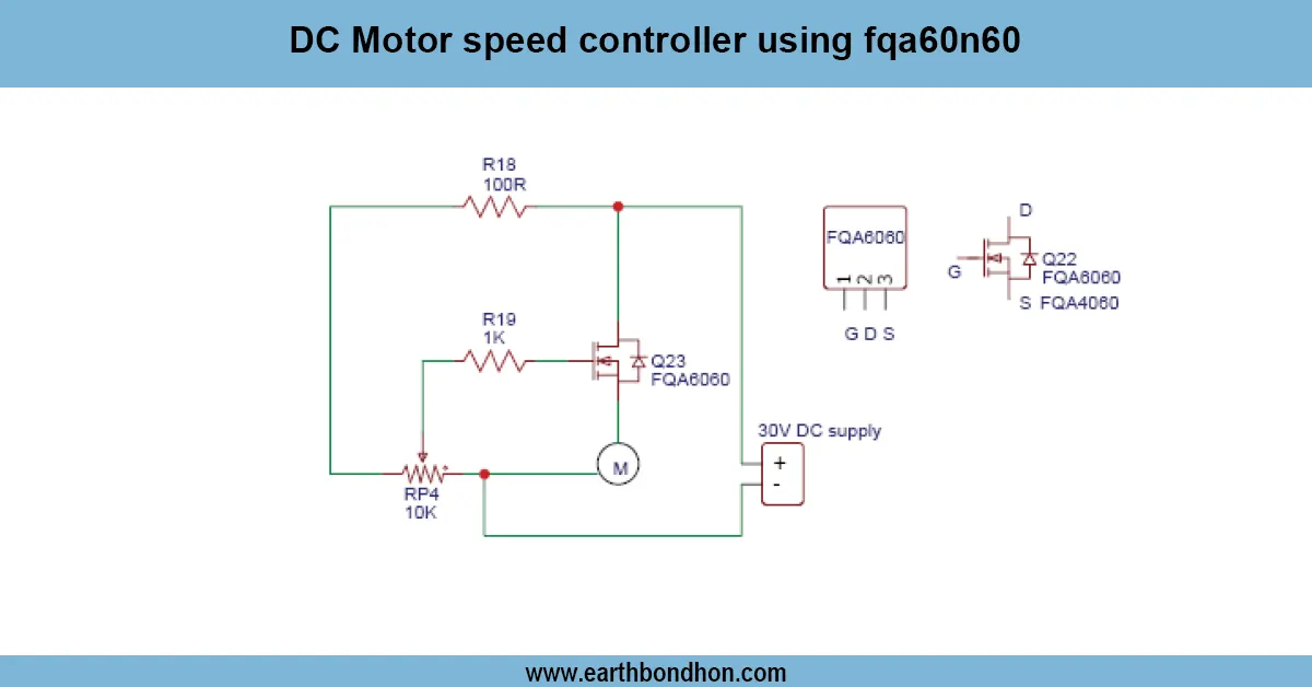
PWM Control for DC Lights
A MOSFET switches the DC light rapidly using PWM. Brightness is controlled by changing the duty cycle of the PWM signal.
TRIAC or MOSFET Switching
TRIACs handle high AC loads safely, triggered via DIAC and RC network. MOSFETs handle DC loads efficiently with minimal heat and power loss.
Circuit Diagram of Simple Dimmer Light
- For AC dimmer: Connect TRIAC in series with AC load.
- Trigger TRIAC with DIAC through RC network controlled by potentiometer.
- For DC dimmer: Connect MOSFET in series with DC load.
- Use PWM generator to adjust MOSFET gate voltage.
- Apply correct AC or DC power supply.
- Brightness should change smoothly with the potentiometer.
Step-by-Step DIY Construction Guide
- Mount TRIAC/MOSFET, DIAC, resistors, capacitors, and potentiometer on breadboard or PCB.
- Connect light load to TRIAC/MOSFET output.
- Wire potentiometer to control triggering or PWM input.
- Apply AC or DC power depending on circuit type.
- Test brightness adjustment with the potentiometer.
- Use heat sinks for high-current applications.
- For AC circuits, enclose in a safe insulated casing.
Applications of Dimmer Light Circuit
- Home lighting adjustment (AC lamps)
- Desk lamps and LED strip brightness control (DC)
- Mood and decorative lighting
- DIY electronics projects
- Small DC fan speed control using PWM
Safety Precautions
- For AC dimmers, ensure proper insulation and avoid touching live wires.
- Use heat sinks where required for TRIAC/MOSFETs.
- Use potentiometers and components with proper voltage/current ratings.
- Test with low-power loads before controlling high-power devices.
Troubleshooting Common Issues
Light Flickering
- Check TRIAC and DIAC wiring.
- Ensure filtering capacitor values are correct.
Limited Dimmer Range
- Adjust RC network or PWM duty cycle range.
TRIAC Not Switching Properly
- Verify gate resistor and DIAC wiring.
- Ensure the TRIAC matches the load current rating.