


LED Blinking Circuit using Transistor Circuit
Build a simple LED blinking circuit using C1815 transistor. Ideal for beginners and hobbyists to learn transistor switching and timing circuits.

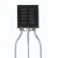
transistor LED flasher
The LED ON/OFF is automatically switched on and off in an LED blinking circuit made with C1815 transistor. It illustrates the fundamental principles of transistor switching and timing as an introduction to electronics learning and amateur projects.
simple LED blinking DIY
The LED Blinking Circuit Using C1815 represents a very simple and easy-going project in electronics that causes an LED to turn on and off automatically. The circuit designed with the C1815 NPN transistor, some resistors, and capacitors forms a simple astable multivibrator. During power, the capacitor fills and empties, creating an ON and OFF effect on the transistor. This makes the attached LED flicker at the rate calculated by the resistor and capacitor values. When these elements are modified, they control the speed of blinking. The circuit is ideal for understanding transistor switching, timing circuits, and principles of oscillation to anyone who is interested in electronics, hobbyists, and the DIY community. It may also be extended to power various LEDs, buzzers, or small loads to create a visual or auditory effect. Components are cheap and can be built on a breadboard or PCB, and are useful as an introduction to oscillating circuits in electronics.
Work / Installation (Inputs → Outputs)
- Power Input → 3–12V DC supply.
- C1815 Transistor → Acts as a switch to control LED.
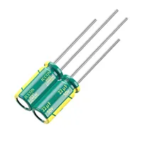
- RC Network → Capacitor and resistors set the blinking frequency.
- LED Output → Blinks ON and OFF according to transistor switching.
- Installation → Assemble components on breadboard or PCB; connect LED with current-limiting resistor; power the circuit; adjust RC values for desired blink rate.
Testing & Final Adjustments
The DC power supply is to be connected after assembly. Automatic blinking of the LED should occur. Measure the rate of blinking and set resistors or capacitors to slow down or speed up. Make sure to confirm that the LED is poled and the C1815 transistor is positioned. Repeat Cycles should be carried out to ascertain consistency. In case of no blinking on the LED, investigate the connections of the capacitor and the resistor. Appropriate testing ensures the appropriate working LED blinking circuit that can be used in hobby projects, learning transistor switching, and testing timing circuits.