SMD LED Tester
Build a simple SMD LED tester to check surface-mount LEDs. Easy, compact, and safe for hobby electronics and DIY LED testing projects.

LED test circuit SMD:
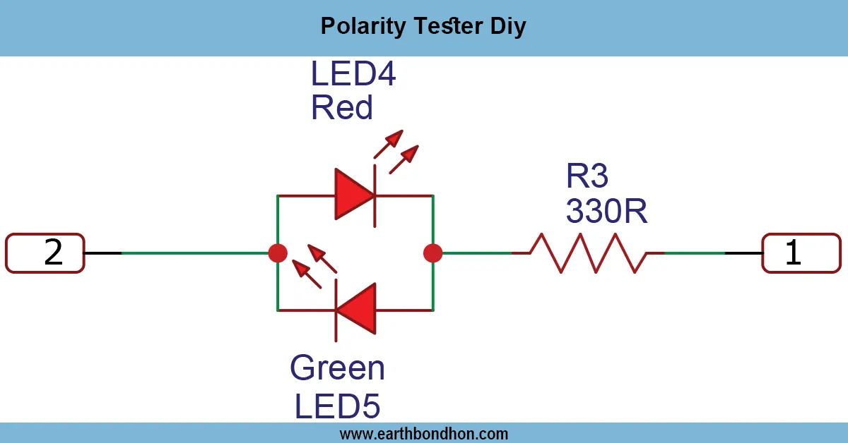
An LED tester is an SMD tool that can be used in a short amount of time to verify the functionality and polarity of surface-mount LEDs. The low-voltage circuit provides a safe way of testing the LEDs without the necessity of soldering.
LED testing DIY project:
The SMD LED Tester is a small and simple circuit that is easy to construct, and it also tests the surface-mount LEDs. It enables a person who is interested in electronics to immediately verify the polarity, brightness, and functionality of SMD LEDs without soldering them to a PCB. It is the ideal tester to use with hobbyists, students, and beginner electronics workers dealing with surface-mount devices. It uses low-voltage DC, usually 3-9V, which is safe to use in the house. All one needs is a simple push-button or battery connection, and the current can be sent through the LED, and it lights up as long as it is operational. Other resistors are provided to keep the current within limits and to save the tester and the nd LED. Portability, safety, and ease of use are the concepts that the design highlights, which is why it makes the tool perfect as a DIY electronics tool, a repair tool, or a tool in the educational field.
⚡ Work & Installation (Input → Output):
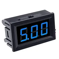
- Power Supply → 3–9V DC battery or adapter.
- Current-Limiting Resistor → Protects LED from excess current.
- Test LED Socket → Place SMD LED in contact pads.
- Push Button (optional) → Controls power flow for testing.
- Output → LED lights up if functional and correctly polarized.
- Installation → Assemble components on small PCB or breadboard for portable use.
Testing & Final Adjustments:
Once assembled, make contact with the tester and a DC power supply, and place the SMD LED on the test pads. Test whether the LED lights are working and of the correct polarity. In case the LED fails to light, examine the battery/power supply, the value of the resistor, and the position of the LED. Make sure that the current-limiting resistor is correct to avoid damage to the LEDs. Check several SMD LEDs to check the consistency of the tester. Protective elements on a tiny PCB or casing to allow it to be used on the move. WSMD LED testerD tester is properly tested, it will be safe, consistent, and efficient in its operation, and this in itself will make it a vital tool for hobbyists and electronics enthusiasts.