


Fire Alarm System Project
Design a simple fire alarm system using BC547 transistor. Detect smoke or heat and trigger buzzer or LED for early fire warning in DIY projects.

smoke sensor alarm using BC547
A smoke detecting or heat detector fire alarm with BC547 detectors produces a buzzer or LED alarm in case of smoke or heat transmission. Atoror will be used as an early warning fire sensor controlled by the sensor output.
transistor-based alarm system
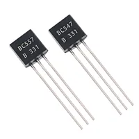
Fire Alarm System with BC547 is a very easy and efficient project that can be used to detect fires in a house, laboratory, or office. BC547 is a type of NPN transistor and it is a switch that can switch on a buzzer or an LED on detecting smoke or heat by a sensor. A smoke sensor (such as an MQ-2) or a thermistor is normally used to detect abnormal conditions in the circuit. Disrupting the buzzer when the sensor output is more than a certain value. The project is a good choice for hobbyists, students, and electronics amateurs because it illustrates the fundamentals of sensor interfacing, transistor switching, and alarm circuits. Components are not expensive, and the design may be made up on a PCB or a breadboard. The sensitivity and response time can be calibrated by adjusting the values of the resistors, so that fire detection can be made reliable.
Work / Installation (Inputs → Outputs)
- Power Input → DC supply (5–12V).
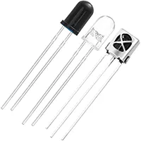
- Sensor Input → Smoke or heat sensor detects fire conditions.
- BC547 Transistor → Switches on when sensor output exceeds threshold.
- Output Device → LED or buzzer activates as fire alarm.
- Installation → Assemble circuit on PCB; connect sensor, buzzer/LED, and power supply; adjust sensitivity resistors for proper triggering.
Testing & Final Adjustments
Once assembled, connect the sensor and DC power supply. Test smoke, or other heat source (be careful) to ensure that the BC547 functions properly and turns the alarm off. When adjusting resistors, adjust to ensure that there are no false alarms. Ensure that, upon the normalization of the conditions, the LED or buzzer is turned off. Test all connections and make sure that there is no overheating of the transistor. The successive test cycles can guarantee reliability, prompt response, and safety. This makes the fire alarm system effective in small-scale usage or in the home.
Frequently Asked Questions - Fire Alarm System Project:
What is BC547 used for?
It is an NPN transistor used to switch the alarm when fire is detected.
Which sensors can I use?
Smoke sensor (MQ-2) or thermistor for heat detection.
Is it suitable for home use?
Yes, ideal for small home or lab applications.
Can I use LED instead of buzzer?
Yes, LED can be used for visual alert.
Do I need calibration?
Yes, adjust resistors for proper sensitivity.
What voltage is required?
Typically 5–12V DC supply.
Is it beginner-friendly?
Yes, simple circuit suitable for students and hobbyists.
Can it detect small fires?
Yes, with properly calibrated sensor and resistor values.
Do I need additional protection?
Optional fuse for safety is recommended.
Is it cost-effective?
Yes, uses inexpensive and readily available components.


