

IR Remote Tester
Test any IR remote using the TSOP34838 sensor. The LED indicator shows signals received, making it ideal for DIY electronics and hobby projects.

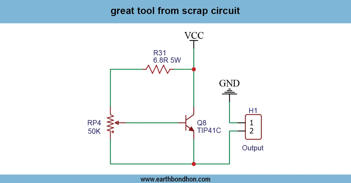
TSOP34838 IR tester circuit
An IR remote tester and TSOP34838 will sense the IR signal of a remote and turn on an LED or a buzzer so that one can quickly test the functionality of a remote used in a hobby or DIY electronics project.
remote control tester project
The IR Remote Tester with TSOP34838 is an easy circuit to use in order to detect and test signals of any infrared (IR) remote control. TSOP34838 is a common high-voltage Ir receiver IC that can be used to demodulate Ir signals at a carrier frequency of 38kHz, used in TVs, AC, and other remote controls. The TSOP34838 takes the modulated IR pulse when the remote is pressed and produces a low pulse as a response to the signal. This can be directly attached to an LED or a buzzer to show that it was received. The circuit is suitable for hobbyists, learners, and electronic lovers who wish to test remote controls or learn about the IR communication. It is a simple, small, and minimalistic design. It is also easy to extend, and a microcontroller can be added to provide more complex IR signal analysis or learning applications, and it is also good at yielding immediate visual feedback.
Work / Installation (Inputs → Outputs)
- Power Input → 5V DC supply to TSOP34838.
- IR Signal Input → Remote sends 38kHz modulated IR.
- TSOP34838 IC → Demodulates and outputs low pulse when signal is received.
- Output Device → LED or buzzer indicates remote signal detection.
- Installation → Assemble on PCB or breadboard; connect LED with current-limiting resistor; power IC with 5V supply; point remote towards sensor and press buttons to test.
Testing & Final Adjustments
When assembled, it has a power supply of 5V DC. Aim the remote control at the TSOP34838 sensor and press any button. Whenever the IC is given a good IR signal, the LED needs to blink or the buzzer needs to sound. Check all buttons to make sure that everything is covered. Turn the LED resistor to the correct brightness. Test a number of remotes as necessary. Make sure the operation of TSOP34838 is not sensitive to any interference from ambient light. The last test constitutes a good IR sensing and working circuit, which can be used in hobby electronics, DIY remote control troubleshooting, and studying IR communication principles.
Frequently Asked Questions - IR Remote Tester:
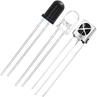
What is TSOP34838?
It is an IR receiver IC that detects 38kHz modulated IR signals.
Can it test TV remotes?
Yes, it works with most TV, AC, and IR remote controls.
Do I need a power supply?
Yes, typically 5V DC for the TSOP34838 IC.
Can it use LED for indication?
Yes, connect an LED with a current-limiting resistor to show detection.
Is it beginner-friendly?
Yes, simple circuit suitable for DIY electronics and hobbyists.
Can it detect multiple remotes?
Yes, it can test different remote controls one by one.
Does ambient light affect it?
Strong sunlight or IR sources may interfere slightly, keep sensor away.
Can I connect a buzzer instead of LED?
Yes, to get audible signal when IR is detected.
Is soldering required?
Optional; can assemble on breadboard for testing purposes.
Is it cost-effective?
Yes, uses minimal and inexpensive components.