


Non-contact AC Line Detector Circuit
Detect AC mains voltage safely without contact using a BC547 transistor. Ideal for DIY electronics, safety testing, and hobbyist AC line detection projects.

non-contact AC detector BC547
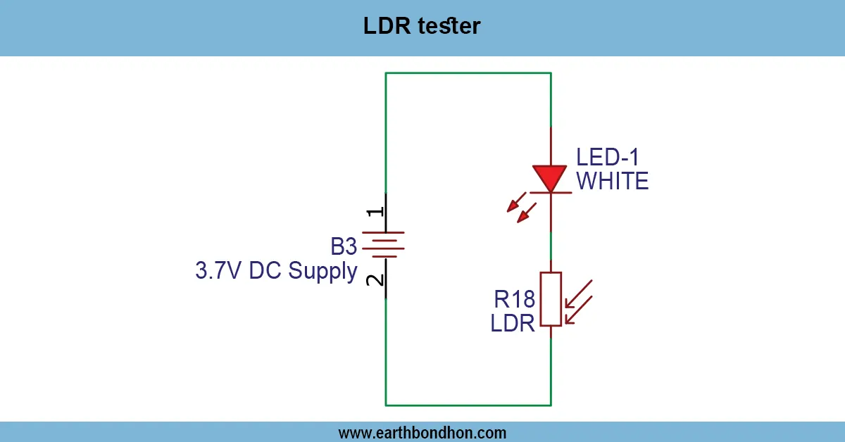
An AC mains voltage detector is a non-contact AC line detector that is operated by the BC547. The capacitive leakage current is then multiplied by the transistor, and an LED or a buzzer is activated to show that there is a safe live voltage.
non-contact voltage tester
You can sense a live AC wire without touching it with the Non-Contact AC Line Detector Circuit, using the BC547. The circuit has a high-value resistor to detect the small capacitive current induced when the detector is close to a live AC line. The signal is amplified by the BC547 transistor and causes an LED or a buzzer to signal the presence of the voltage. This circuit is small, easy to use, and suitable for hobbyists, students, and DIYers who would like to check AC lines, troubleshoot, or check wall sockets without having to touch live wires. When the probe is near a live wire, the LED is lit. The choice of components is proper with no false triggering. This device is also applicable to low current applications and must not be allowed to come into direct contact with high power lines.
Work / Installation (Inputs → Outputs)
- Detection Probe → Held near the AC line.
- High-Value Resistor → Senses capacitive leakage current.
- BC547 Transistor → Amplifies the signal.
- Indicator → LED or buzzer alerts presence of AC voltage.
- Power Supply → Low-voltage DC supply powers transistor circuit.
- Installation → Assemble on PCB or breadboard, connect indicator, test near live AC wire, and ensure insulation and safety.
Testing & Final Adjustments
Once it has been assembled, touch the detection probe to a live AC wire. The LED or buzzer must come on, which means that there is AC. Modify the values of resistors or the sensitivity of transistors in case the indicator is activated too soon or does not react. To prevent electric shock, it must not be used to measure high currents or to touch the mains. It is well insulated, enclosed safely, and powered with low voltage, which ensures reliable operation. Test against different AC sources so that the consistency of detection can be ensured. Final-tuning is used to prevent false triggers caused by nearby electrical devices, whilst at the same time ensuring safety and precision.