Humming Free Ceiling Fan Regulator Circuit
Build a humming-free ceiling fan regulator circuit for smooth speed control. Step-by-step DIY guide, components, working principle, and FAQs included.

What Is a Humming Free Ceiling Fan Regulator Circuit?
A humming-free ceiling fan regulator circuit is an electronic circuit that can be used to control the speed of an AC fan with minimal humming noises by resistive voltage control or inefficient TRIAC firing.
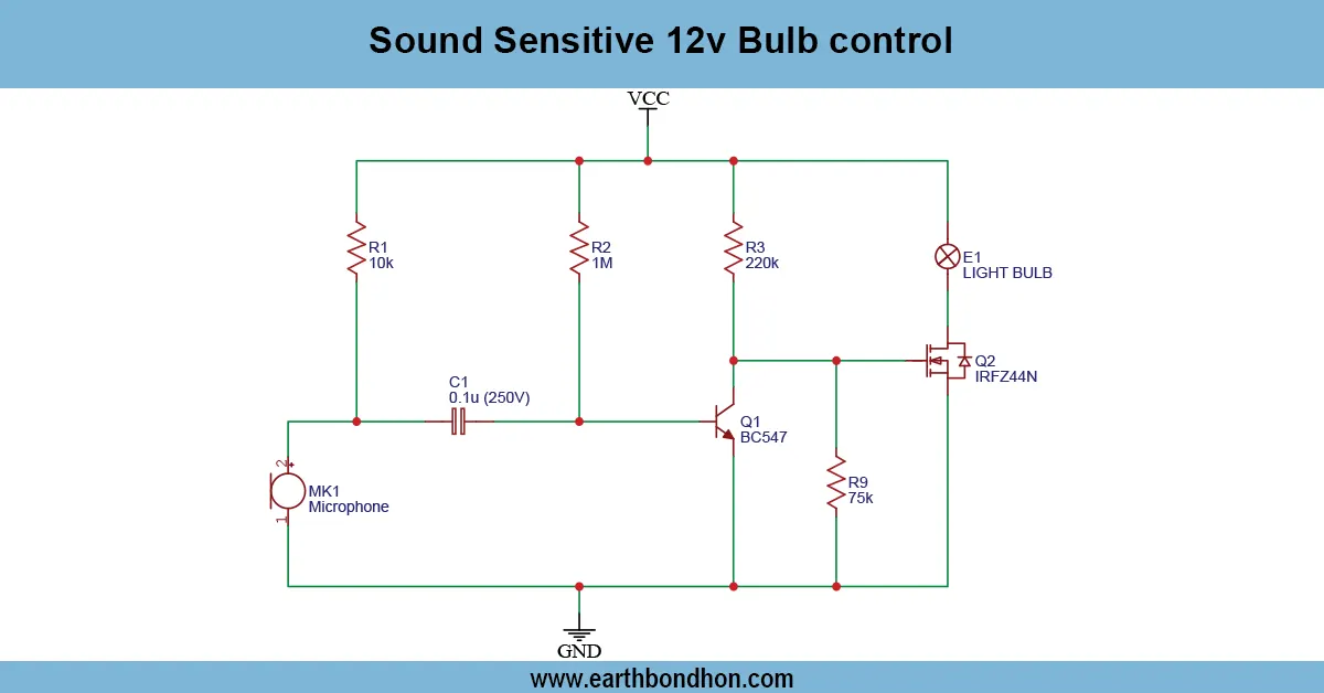
triac dimmer humming free fan regulator circuit
A humming-free ceiling fan regulator circuit is created to control the speed of an AC ceiling fan without the irritating humming sound that is generated by the traditional regulators. This self-assembled circuit is a phase angle control based on a TRIAC, diac triggering, and snubber networks to minimize electrical noise and mechanical vibrations.
The humming free ceiling fan regulator circuit operates by adjusting the amount of voltage on the fan motor provided by the AC supply. Old-fashioned resistive types of regulators usually produce a buzzing effect, as a result of sudden drops in voltage. The voltage is then adjusted gradually using a TRIAC-based regulator, which makes them run silently and use less energy. The construction of this circuit can be suggested to hobbyists, electricians, and all people who want to make a ceiling fan that is better and can be used without making a noise.
Humming-Free Fan Regulator Circuit
A noise-free, energy-efficient fan speed controller using TRIAC–DIAC phase control and snubber network for smooth and silent operation.
Advantages of a Humming-Free Fan Regulator
- Silent Operation: Eliminates buzzing or humming sound.
- Energy Efficient: Lower power loss compared to resistive regulators.
- Smooth Speed Control: Gradual speed change from low to high.
- Longer Fan Life: Reduces stress on the fan motor.
- Cost-Effective Upgrade: Low-cost and DIY-friendly design.
Components Required for DIY Circuit
| Component | Quantity | Purpose |
|---|---|---|
| TRIAC (BT136 / BTA16) | 1 | Switches AC voltage to fan |
| DIAC (DB3 / BTA08) | 1 | Triggers TRIAC |
| Potentiometer (100kΩ) | 1 | Adjusts fan speed |
| Capacitors (0.01µF – 0.1µF, 400V) | 2 | Phase control & snubber |
| Resistors (100Ω – 1MΩ) | Various | Timing and protection |
| Snubber Network (R-C) | 1 | Reduces humming & spikes |
| PCB / Perfboard | 1 | Circuit assembly |
| Enclosure | 1 | Safe AC housing |
| Fuse | 1 | Overcurrent protection |
Working Principle of the Circuit
AC Input and TRIAC Stage:
AC mains supply powers the TRIAC, which switches ON/OFF rapidly to control the average voltage to the fan.
Phase-Control for Speed Adjustment:
A variable RC network sets the delay.
DIAC triggers the TRIAC at adjustable firing angles:
• Early firing → higher speed
• Late firing → lower speed
Snubber Network:
RC snubber across the TRIAC reduces voltage spikes and motor humming.
Output to Fan:
Smooth AC waveform delivered to the fan for silent operation.
Safety and Enclosure:
A fuse and insulated enclosure are necessary for safe AC operation.
Circuit Diagram Explanation
AC Mains → Fuse → TRIAC → Fan
Potentiometer + Capacitor → DIAC → TRIAC Gate
Snubber Network (RC) → Across TRIAC MT1–MT2
Step-by-Step Construction Guide
- Connect fuse in series with AC mains; connect live wire to TRIAC MT1.
- Build trigger circuit: Potentiometer + capacitor → DIAC → TRIAC gate.
- Install RC snubber across TRIAC MT1–MT2.
- Connect fan: Live → TRIAC MT2, Neutral → directly to fan.
- Power ON and test. Adjust the potentiometer for smooth and silent speed control.
Applications
- Ceiling fan speed control
- Exhaust fan regulation
- Small AC motor speed control
- Energy-saving fan operation
- DIY home electronics projects
Troubleshooting Tips
| Problem | Solution |
|---|---|
| Fan hums slightly | Adjust snubber RC values |
| Fan doesn’t run at low speed | potentiometer wiringwiring & DIAC trigger |
| Fuse keeps blowing | Check TRIAC rating & wiring |
| Fan jerks or vibrates | Verify TRIAC and snubber installation |
| Fan doesn’t respond | Check DIAC, AC connections, and RC network |