12V Negative Voltage Regulator
Learn how a 12V negative voltage regulator works. Circuit, applications, pinout, and FAQ included. Ideal for power supply stabilization in electronics projects.
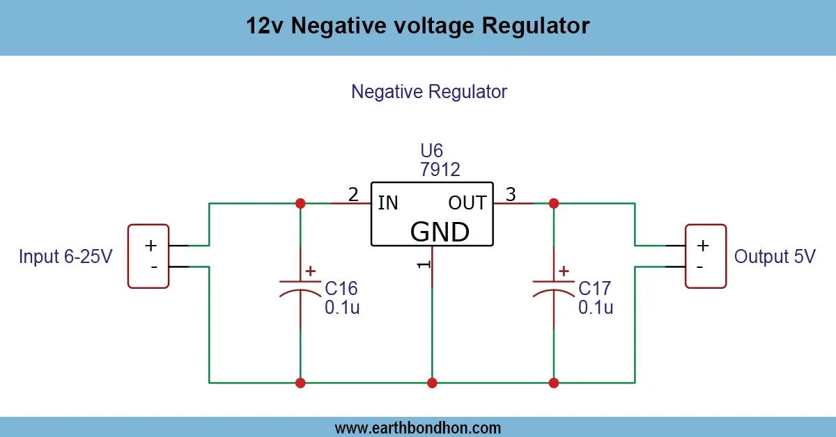
negative voltage converter
To assure a stable 12V output, the 12V Negative Voltage Regulator circuit is important to the analog and audio electronics. It also protects devices against variations in voltage and provides stable operations. This tutorial and design guide you through how to design, compute, and test a very simple 12V regulator circuit utilizing elements such as the LM7912, capacitors, and an appropriate transformer or DC power supply.
Formula & Table Summary:
- Output Voltage (Vout) = -12V (regulated by LM7912)
- Input Voltage (Vin) = -14V to -30V DC
- Capacitor Input: 0.33μF (recommended at regulator input)
- Capacitor Output: 0.1μF (recommended at regulator output)
- Max Output Current: ~1A (with proper heat sink)
12v negative voltage regulator
To obtain a stable 12V DC signal out of a higher negative DC supply, a 12V Negative Voltage Regulator may work with ICs, such as LM7912. These regulators are critical in applications where two polarity power supplies are critical, like in an operational amplifier application. Input fluctuations and different load currents can make the output stable; due to this, sensitive components are protected against voltage destruction by the regulator.
7912 voltage regulator circuit
| Parameter | Value | Unit |
|---|---|---|
| Input Voltage | -18 | V |
| Output Voltage | -12 | V |
| Output Current | 0.5 | A |
| Ripple Voltage | 50 | mV |