


Proximity Sensor Circuit
Build a simple proximity sensor circuit using a BC547 transistor to detect nearby objects. Ideal for DIY electronics, hobby projects, and automation experiments.

low-voltage proximity detector
A contactless proximity sensor is based on BC547. The transistor can be used to control a load when reflected light or IR signals are used to detect the presence of an object, which is why it is beneficial in DIY detection systems.
IR BC547 sensor project
The Proximity Sensor Circuit with BC547 is an easy-to-build project that detects objects without physically touching them in the vicinity. The circuit can sense the change of light or reflected signal by using infrared LEDs, photodiodes, or LDRs in combination with BC547 as the primary switching transistor. When an object approaches the sensor, the photodiode/LDR notices the reflected light to activate the BC547 transistor, which then activates a load connected to it, e.g., an LED, buzzer, or relay. The project is a good fit for hobbyists, students, and DIY electronics lovers who will be interested in experimenting with automation and sensing circuits. A better selection of resistors guarantees the proper working of the transistor and the load. Low-voltage DC can be used to power the circuit, and thus it is safe and easy to implement on a breadboard or PCB. It also illustrates applications of transistors in sensing and switching in the real world and offers a practical learning process in electronics.
Work / Installation (Inputs → Outputs)
- Power Supply → Low-voltage DC (5–12V).
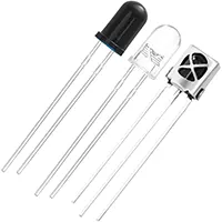
- IR LED / Photodiode / LDR → Detects reflected light from nearby object.
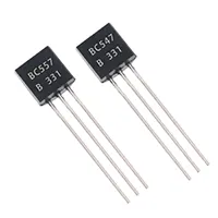
- BC547 Transistor → Acts as a switch to trigger the load.
- Resistors → Limit current to LEDs and base of transistor.
- Output Load → LED, buzzer, or relay activated on detection.
- Installation → Assemble components on breadboard/PCB, align sensor and emitter, connect power, and test object detection range.
Testing & Final Adjustments
Connect after building and turn on the circuit, and take an object towards the sensor. Note that the load (LED /buzzer) comes on. Adjust the values of the resistors to control the sensitivity. In the case of IR sensors, alignment of the emitter and detector is required. Check the switching of the transistor using the voltage collector and base. Test on varying distinctions to ensure sound detection. Safe operation, sensitivity adjustment, and functionality in DIY automation, alarm, or detection projects are all facilitated by proper testing. Detection range and responsiveness can be enhanced by fine-tuning the resistor values to use or even by the location of the photodiode.
Frequently Asked Questions - Proximity Sensor Circuit:
What is a proximity sensor?
A device that detects nearby objects without physical contact.
Which transistor is used?
BC547 NPN transistor as a switch.
What components are required?
BC547, IR LED or LDR, resistors, LED/buzzer/load, power supply.
What voltage is needed?
5–12V DC is ideal for safe operation.
Can it detect all objects?
It detects objects that reflect light or IR signals.
Is it beginner-friendly?
Yes, simple assembly on breadboard with low voltage.
Can I use a relay as output?
Yes, BC547 can drive a small relay to control higher loads.
Can sensitivity be adjusted?
Yes, by changing resistor values or sensor alignment.
Applications?
DIY alarms, automatic lights, hobby electronics, object detection.
Do I need special tools?
No, basic electronics tools like multimeter and soldering are sufficient.