Component Tester
Build a simple component tester circuit to check transistors, diodes, resistors, and capacitors. Ideal for hobbyists and electronics beginners.

transistor diode tester circuit
A component tester circuit is a circuit used in rapid testing of electronic component including transistors, diodes, resistors and capacitors. It recognizes errors, polarity, and approximate values of DIY electronic projects.
component tester DIY circuit
The Component Tester Circuit is a useful device that can be used by electronics enthusiasts to test assorted electronics components such as transistors, diodes, resistors, and capacitors. It is able to detect faulty or functioning parts using a multimeter in a short time. This circuit is more commonly a combination of ICs (such as CD4066 or LM339), transistors (BC547/BC557), resistors and LEDs to show component type and condition.
The tester is a device that is used by applying a low voltage to the component being tested and seeing the LED or digital result. In the case of transistors, it is able to identify either PNP or NPN types and gain (hFE). In case of diodes and capacitors it gives information of polarity and approximate value.
It is an educational project, is low cost and can be used in DIY electronics laboratories to show novices the properties of components, troubleshooting and testing circuits before assembly.
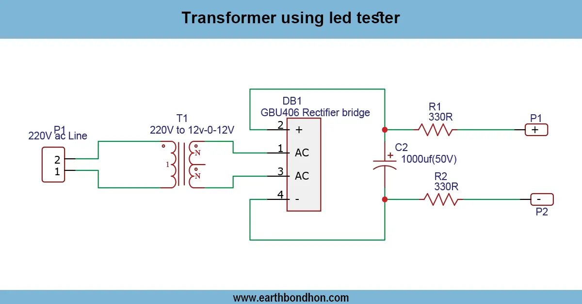
Work / Installation (Inputs → Outputs)
- Power Input → Typically 5V–12V DC supply.
- Component Slot/Probes → Place the component to test.
- Circuit Logic → Transistors and IC detect component type and properties.
- Output Display → LEDs or digital display indicate component type, polarity, and status.
- Installation → Mount on PCB or breadboard; ensure correct IC and transistor orientation.
Testing & Final Adjustments
Once component testerster has been assembled, supply power to the circuit, and place known parts to check it. Check LEDs or digital output to verify that correct polarity of PNP/NPN transistors, polarity of diodes or a capacitor is indicated. Vary resistors when sensitivity is either high or low. Try different resistors and capacitors in order to prove approximate values. Make sure that connections are firm and make sure that the components are firmly fixed. In digital formats, both the logic of the microcontroller or IC used and its calibration should be performed. The use of various types of components in testing guarantees consistency in results. Adequate calibration and testing offer an effective circuit troubleshooting aid, which save time and limit assembly mistakes.