Solar Emergency Light Circuit
Build a reliable Solar Emergency Light Circuit: solar panel sizing, battery selection, charge controller options (TP4056/MPPT/PWM), LED driver, schematics, and safety tips.

What is a Solar Emergency Light Circuit?
- Harvests solar energy (panel)
- Stores energy in a rechargeable battery (Li-ion, LiFePO4, or SLA)
- Controls charging safely (charge controller or IC)
- Powers LED lighting during darkness or outages
- Automatically turns the light on/off based on ambient light or a control signal
A Solar Emergency Light Circuit is a power management system that:
Core goals: safe charging, battery protection, efficient LED driving, and automatic switching.
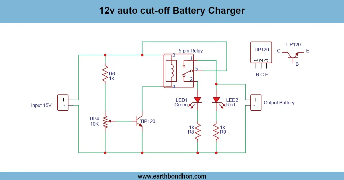
solar emergency light circuit diagram
A Solar Emergency Light Circuit is a set of self-powered lighting installed to supply reliable lighting in case of failure of mains power. It is a solar panel, charge controller, rechargeable battery, and LED lamp with an automatic switching mechanism in that the lights charge during the day and automatically switch on at dusk or a power outage. Solar emergency lights may be miniature, portable (single high-power LED, plus small Li-ion cell) or home-scale, with a battery bank of 12 V, and multiple LEDs. Efficiency, run time, charging speed, and safety depend on the choice of the topology - compact TP4056 + boost driver with a 1S Li-ion pack or a 12 V SLA with a PWM charger or MPPT-based multi-cell Li-ion system. This tutorial not only takes you through the practical circuits, component selections, sizing calculations, assembly hints, and safety measures to enable you to complete a robust Solar Emergency Light Circuit to meet your wishes.
Key Design Choices (Battery Chemistry, Voltage, and Lamp Type)
1S Li-ion (3.7 V):
Compact, high energy density. Needs TP4056 CC–CV charger + boost converter (5–12V). Great for small emergency lamps and portable units.
12 V SLA (Sealed Lead Acid):
Cost-effective, robust, suitable for large home/emergency lights. Heavy but simple charging using PWM chargers.
LiFePO4 (3.2–3.3 V per Cell):
Highly safe, long cycle life, stable. Needs specific LiFePO4 charger/BMS.
LED Types and Drivers
Use high-efficiency LEDs (CREE / Nichia / Samsung) + constant-current drivers for the best performance.
- Small systems: boost converter with current limit.
- 12V systems: series/parallel LED strings with LED driver or resistors.
Core Functional Blocks of the Circuit
Solar Panel & Blocking Diode
Prevents backflow at night. Panel voltage must match charger/battery type.
Charge Controller Options
- TP4056: For 1S Li-ion, simple and cheap.
- PWM Charger: For 12V SLA systems.
- MPPT: Most efficient for multi-cell and LiFePO4.
Battery & Protection
Use BMS, fuses, PTCs, MOSFET switches for safe operation.
Load Output & Switching
- Automatic ON/OFF using LDR + MOSFET.
- Manual switches or remote options.
- PWM dimming for brightness control.
Three Practical DIY Circuit Options
Option A — Small 1S Li-ion System (TP4056 + Boost)
Best for pocket emergency lamps, 1–3W LED.
Core Components:
- 6V solar panel
- TP4056 charger
- 18650 Li-ion battery
- Boost converter (MT3608)
- 1–3W LED + driver
- Schottky diode
Textual Schematic:
Solar Panel → Diode → 5V Regulator → TP4056 IN+
TP4056 BAT+ → Li-ion Cell → Boost Converter → LED Driver → LED
LDR Sensor → MOSFET → LED Control
Option B — 12V SLA with PWM Charger
Best for large home emergency lights.
Core Components:
- 18V solar panel
- PWM charge controller
- 12V 7Ah SLA battery
- MOSFET switching + LDR
Textual Schematic:
Solar Panel → PWM Controller → 12V Battery
Battery → Fuse → MOSFET → LED Driver → LED Array
LDR → Gate of MOSFET
Option C — 2S/3S Li-ion or LiFePO4 + MPPT
Core Components:
- MPPT charge controller
- BMS with balancing
- LiFePO4 battery pack
- Constant-current LED driver
- Microcontroller for smart control
Textual Schematic:
Solar Panel → MPPT → Battery Pack (+BMS)
Battery → Fuse → Constant Current LED Driver → LED Array
MCU / LDR → MOSFET Switch
Sizing Guide (Solar, Battery, LED)
Example calculation for a 10W LED running 4 hours:
- Energy needed = 10W × 4 = 40 Wh
- With margin = ≈ 50 Wh
- Battery (12V): 50 / 12 ≈ 4.17 Ah → choose 7 Ah
- Panel: ≈ 20–30 W (depending on sun hours)
Automatic Dusk/Dawn Switching
- LDR + LM358 comparator
- Microcontroller (ESP/Arduino)
- RTC (DS3231) for timing events
PCB & Wiring Best Practices
- Short, thick wires for battery & solar lines
- Place decoupling capacitors near ICs
- Use fuses & proper insulation
Troubleshooting Common Issues
- Battery not charging → check polarity & PV voltage
- LED flickering → low battery or loose wiring
- TP4056 heating → ensure input is ≈ 5V