

Touch Switch Circuit
Control LEDs or small devices with a fingertip using a 2N2222A transistor touch switch circuit, ideal for DIY electronics and home automation projects.

DIY touch switch circuit:
The 2N2222A touch switch circuit allows users to turn LEDs or small devices on and off with a simple fingertip touch. Using the 2N2222A NPN transistor as a switch, the circuit detects a touch on the sensor pad and conducts current to illuminate the load. This compact and energy-efficient design is perfect for DIY electronics, home automation, and educational projects. The guide explains the working principle, input-to-output connections, and step-by-step installation, helping beginners and hobbyists implement a reliable, mechanical-free switching solution for small loads and LED lighting.
Low-power touch switch:
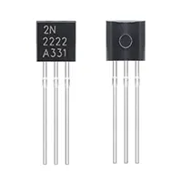
The 2N2222A touch switch circuit is a simple and efficient way to control LEDs or small devices using just a fingertip. It uses the 2N2222A NPN transistor as a switch that responds to a touch on the sensor pad, allowing current to flow through the LED or connected load. This eliminates the need for mechanical switches, making it ideal for DIY electronics projects, home automation, and educational experiments. The touchpad is connected to the base of the transistor through a current-limiting resistor, while the collector and emitter handle the load current. The circuit operates on a 3–12V DC power supply, depending on the load requirements. Sensitivity can be adjusted by changing the base resistor value to suit different touch conditions. For higher-power devices, a relay or MOSFET driver can be added. Installation is easy on a breadboard or PCB, and proper insulation ensures safety and long-term durability. This compact, energy-efficient touch switch provides a modern, mechanical-free solution for controlling small devices with a simple fingertip touch, offering reliable and repeatable performance for hobbyists and beginners.
⚡ Work & Installation (Input → Output):
The circuit operates by connecting a touchpad to the base of the 2N2222A transistor through a current-limiting resistor. When the pad is touched, a small base current flows, turning the transistor on and allowing collector-to-emitter current to power the LED or small load. Removing the touch turns off the transistor, switching off the load. Installation involves placing the 2N2222A, resistor, and touchpad on a breadboard or PCB. The circuit is powered by a 3–12V DC source, depending on the load. The touchpad acts as the input, and the LED or device is the output. For higher loads, a relay or MOSFET driver can be added. Proper wiring, insulation, and component placement ensure long-term reliable operation, making it ideal for DIY and home automation applications.
Testing & Final Adjustments:
After assembling the 2N2222A touch switch, power the circuit and touch the pad. The LED or device should turn on with a touch and off when released (or toggle if designed for bistable operation). If it does not respond, check the connections, especially the resistor between the touchpad and transistor base, and ensure correct transistor orientation. Adjust the base resistor to increase or decrease touch sensitivity; higher resistance reduces sensitivity, while lower resistance increases it. For higher-power loads, connect a relay or MOSFET driver. Verify the transistor does not overheat and that all connections are secure. Mount the components on a PCB and insulate exposed wiring for durability. Once tested and adjusted, the touch switch provides reliable, energy-efficient, mechanical-free control for LEDs or small appliances, suitable for hobbyists and beginners who want a simple, responsive, fingertip-activated switching solution.