


Power Tesla Coil
Build a transistor-based Tesla coil using a simple transistor oscillator circuit to generate high-voltage sparks for educational and DIY electronics projects.

Small Tesla coil project:
A transistor base Tesla coil is a small, high-voltage generator which utilizes high frequency AC generation by a transistor oscillator. In contrast to the conventional spark-gap Tesla coils, this design incorporates the use of a transistor or transistors to carry current through the primary coil at a high rate and cause a high voltage to be produced in the secondary coil. It is perfect in educational demonstrations, in DIY electronics projects, and in hobbyists that are investigating high voltages safely. The transistor design can be used to make the Tesla coil compact, energy efficient and controllable. This project guide covers the principle of operation, transistor choice, coil wiring, and safe operation and assists enthusiasts to build a functional mini Tesla coil to learn and experiment.
High-voltage transistor oscillator:
A transistor base Tesla coil is a small and powerful generator that operates using a transistor oscillator and produces a high voltage high-frequency AC voltage in the second coil. It also uses a transistor and does not use an arc or gapping method of switching, as in the traditional spark-gap Tesla coils, instead causing current to flow in and out of the primary coil to produce a magnetic field, which causes high voltage to be induced in the secondary coil. It is a design that is suitable to be used by hobbyists, students, and electronic enthusiasts who require a small, efficient and controllable Tesla coil to be used in demonstrations in education, or in their own experiments. The coil is made up of a primary winding which is linked with the transistor circuit and a secondary winding which is made up of numerous turns of fine wires usually topped by a toroid in order to smooth the output voltage. The transistor base resistor should be tuned properly, the primary coil turns, and the tank capacitor tuned to be able to guarantee effective oscillation and maximum spark generation. By building a transistor base Tesla coil with great care, insulation, and caution, it is possible to produce visible sparks, light small bulbs wirelessly, and have direct real-world experience with high-frequency high-voltage electronics.
⚡ Work & Installation (Input → Output):
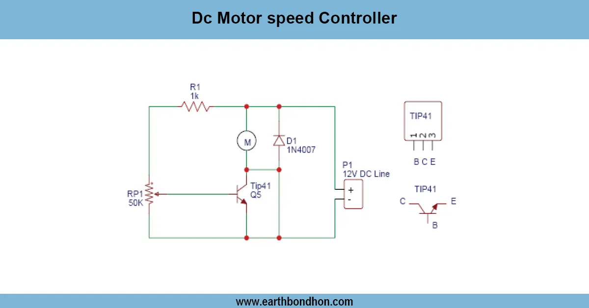
The transistor base Tesla coil operates by DC voltage applied to a transistor oscillator circuit that is connected to the primary coil. The transistor switches current easily on and off, producing a high-frequency magnetic field. This produces and drives a high voltage in the second coil, which can produce visible sparks or light tiny fluorescent bulbs at a distance. The main winding is attached to the transistor collector (or drain in the case of MOSFET), and the base (or gate) is driven by a resistor and capacitor network to form an oscillation. The secondary coil consists of the fine wire wound on a cylindrical shape and the top load (toroid) is used to smooth the voltage to produce more sparks. Primary and secondary Coils should be carefully wired with good insulation, and every connection should be made in such a way that it can withstand high voltage. The Tesla coil should be operated with an adequate DC power supply, and a lot of caution is essential when using the coil.
Testing & Final Adjustments:
Once the base Tesla coil of the transistor is put together, apply the DC supply with caution. Ascertain whether the primary coil oscillates or not (with an oscilloscope preferably) or monitor small sparks at the end of the secondary coil. When there is no oscillation, then modify the base resistor or capacitor value to provide correct transistor switching. Ensure that connections are correct, the transistor is of the supply voltage and current, and that the primary coil is well spaced between the secondary to avoid arcing. Initially, test the coil at low supply voltage and then slowly increase the supply voltage to the required level, taking precautionary measures. All exposed wires should be insulated, and a safe distance should be observed between the high-voltage secondary output and the exposed wires. The correct tuning of the primary coil, capacitors, and transistor choice is the guarantee of the maximum spark length and efficiency. Aftthe er test, the Tesla coil on the base of a transistor can offer a small, steady, and visually stunning high voltage demonstration, both in education and DIY projects and hobby electronics. Always make sure to be careful not to get tanelectric shock.
Frequently Asked Questions - Power Tesla Coil:
What is a transistor base Tesla coil?
A small Tesla coil that uses a transistor oscillator to generate high-voltage AC.
How does it work?
The transistor switches current rapidly through the primary coil, inducing high voltage in the secondary.
Which transistors are used?
High-speed, high-voltage transistors such as 2N3055, TIP31, or MOSFETs.
Can it generate visible sparks?
Yes, small sparks appear at the secondary tip or light nearby bulbs.
Is it safe?
Safe if operated at low current and proper insulation is used; caution is required.
Can it power LEDs or bulbs wirelessly?
Yes, small fluorescent or neon bulbs can light up near the coil.
Is it suitable for beginners?
Yes, with proper supervision and understanding of high-voltage safety.
Do I need a capacitor in the primary?
Yes, a tank capacitor helps create proper oscillation in the primary circuit.
Can I use it for experiments?
Yes, ideal for educational and hobby experiments with high voltage.
Does it require a special power supply?
A DC supply suitable for the transistor ratings and primary coil current is needed.