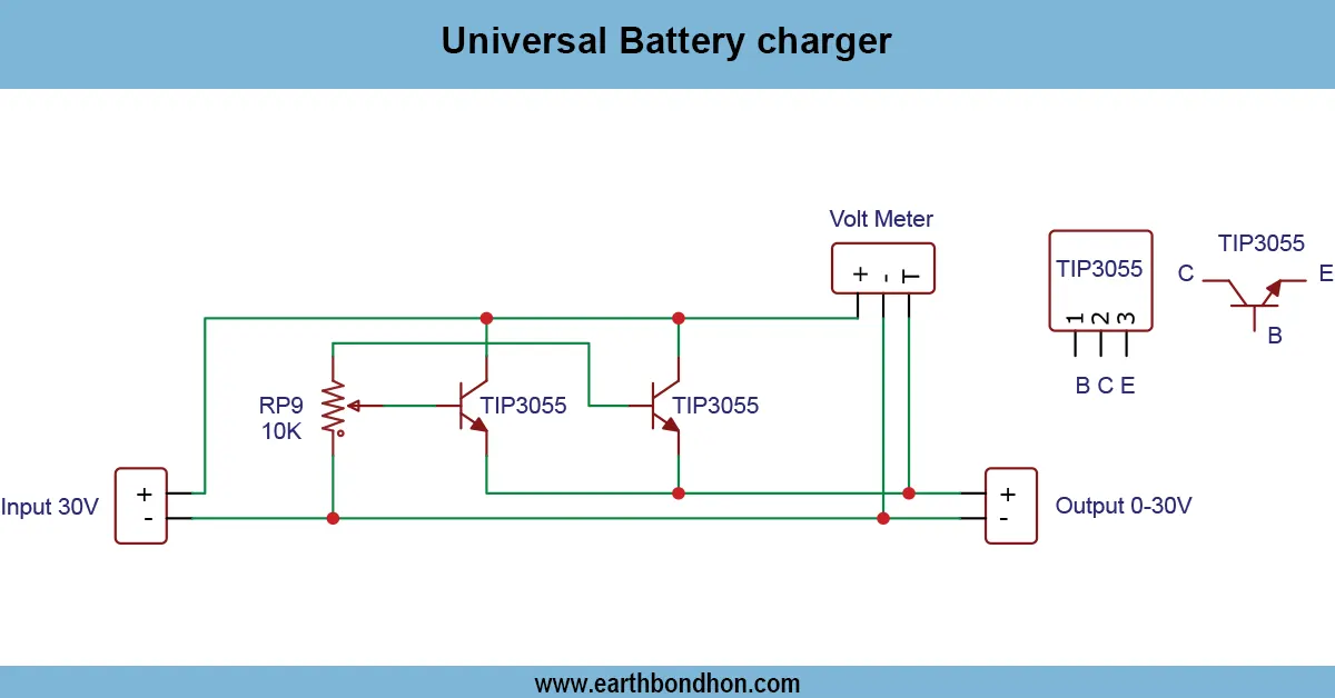
Current Voltage Adjustable Power Supply 0-30V 10A
Build a 0-30V 10A adjustable power supply with precise voltage and current control. Step-by-step guide with circuit diagram, components, working principle, and safety tips for electronics projects.

Introduction to Adjustable Power Supplies
Variable power supplies find application in electronics laboratories, test equipment, and in home projects. The 0-30 V 10A power supply will enable users to safely supply different circuits with varying voltage and current. The supply achieves stability in the volume of voltages at different load conditions because it uses the linear regulators, MOSFETs, T s, and potentiometers.
power source battery charger power supply
A Current and Voltage Adjustable Power Supply 0 -30 V 10 A is needed in electronics testing, DIY work, and laboratory work. It gives you the ability to adjust the voltage and current in a fine manner to safely energize devices or circuits being tested. Being capable of supplying up to 10A, it allows serving loads with high-power requirements, and may provide such protection features as short-circuit protection and overcurrent protection. The voltage regulators, MOSFETs, and potentiometer combinations are used in this project in order to make correct adjustments. Here, we discuss the parts required, how it works, circuit board, assembly guidelines, calibration, and troubleshooting procedures, and you will have a good, safe, and adjustable power supply unit that can work with a variety of electronics,s, papers, and projects.
Features of the 0–30V 10A Power Supply
Adjustable Voltage Control
- Output voltage adjustable from 0V to 30V.
- Fine adjustment using potentiometer.
Adjustable Current Limit
- Set maximum output current to protect devices.
- Automatic current limiting with LED indicator.
High Power Handling
- Capable of delivering up to 10A.
- Includes heat sink and cooling fan for high-power operation.
Components Required
LM338 / LM350 / MOSFET or High Current Regulator
Handles high current output with stable voltage regulation.
Transformer and Rectifier
Step-down transformer provides DC input after AC to DC conversion using a bridge rectifier.
Heat Sink and Cooling Fan
Prevents overheating of regulator and MOSFET.
Potentiometers for Adjustment
Two potentiometers: one for voltage control and one for current limit.
Capacitors and Resistors
Smooths output voltage and controls current limit settings.
Display Meters (Optional)
Digital/analog voltmeter and ammeter to monitor output.
Working Principle
Voltage Regulation
- Linear regulator or MOSFET adjusts output voltage.
- Feedback loop ensures stable voltage at output terminals.
Current Limiting Mechanism
- Current is sensed using a low-ohm resistor.
- When the current exceeds a set limit, the regulator reduces the output current.
Protection Features
- Overcurrent protection.
- Short-circuit protection.
- Thermal shutdown to prevent overheating.
Circuit Diagram and Assembly Steps
Connecting Transformer and Rectifier
- Connect the AC mains to the primary of the transformer.
- Use a bridge rectifier to convert AC output to DC.
Wiring Voltage and Current Control
- Connect the regulator/MOSFET to the rectified DC.
- Wire potentiometers for voltage and current adjustment.
Connecting Meters and Load
- Connect the voltmeter across the output terminals to monitor the voltage.
- Ammeter must be connected in series with the output load.
Testing and Calibration
- Power up the circuit without a load.
- Adjust the voltage potentiometer to set the desired output.
- Apply a small load and adjust the current limit potentiometer.
- Test with full load and ensure stable operation without overheating.
Applications
- Electronics lab power supply.
- DIY projects requiring variable voltage and current.
- Battery charging and testing.
- LED strip powering.
- Prototyping circuits with precise power requirements.
Safety Precautions
- Ensure proper grounding and insulation.
- Use fuses on both input and output for protection.
- Do not touch live circuits while testing.
- Install the heat sink and cooling fan properly.
- Never exceed regulator or MOSFET ratings.
Troubleshooting and Maintenance
- No output: Check transformer, rectifier, and all wiring.
- Output fluctuates: Inspect the feedback loop and the potentiometer.
- Overheating: Check heat sink, fan, and current limit setting.
- Wrong voltage: Recalibrate voltage pot.
- Shorted output: Ensure load does not exceed 10A.
Frequently Asked Questions - Current Voltage Adjustable Power Supply 0-30V 10A:
What is the maximum voltage output?
The adjustable power supply can provide 0-30V output.
What is the maximum current output?
The power supply can deliver up to 10A current.
Can I use it for battery charging?
Yes, but ensure voltage and current are set according to battery specifications.
What type of regulator is used?
LM338, LM350, or high current MOSFET-based regulators can be used.
Are display meters necessary?
No, but voltmeter and ammeter help in monitoring output accurately.
Is cooling required?
Yes, heat sinks and fans are required to prevent overheating at high current.
Can this power supply handle LED strips?
Yes, it can power LED strips requiring up to 30V and 10A.
Can I adjust voltage and current simultaneously?
Yes, two separate potentiometers control voltage and current independently.
Is this project suitable for beginners?
Yes, but basic electronics knowledge is required for assembly and calibration.
What safety precautions should I take?
Use fuses, proper insulation, grounding, and avoid exceeding component ratings.