
DC Motor Forward Reverse Control
Control a DC motor’s forward, reverse, and stop functions using relays. Simple and cost-effective circuit ideal for small robotics and automation projects.

forward reverse motor relay DIY
Simple forward, reverse, and stop operations are possible with a DC motor control circuit that uses relays. The motor polarity changes, and the relay is supplied in a safe manner that offers low-cost automation of small motors.
stop-start motor relay circuit
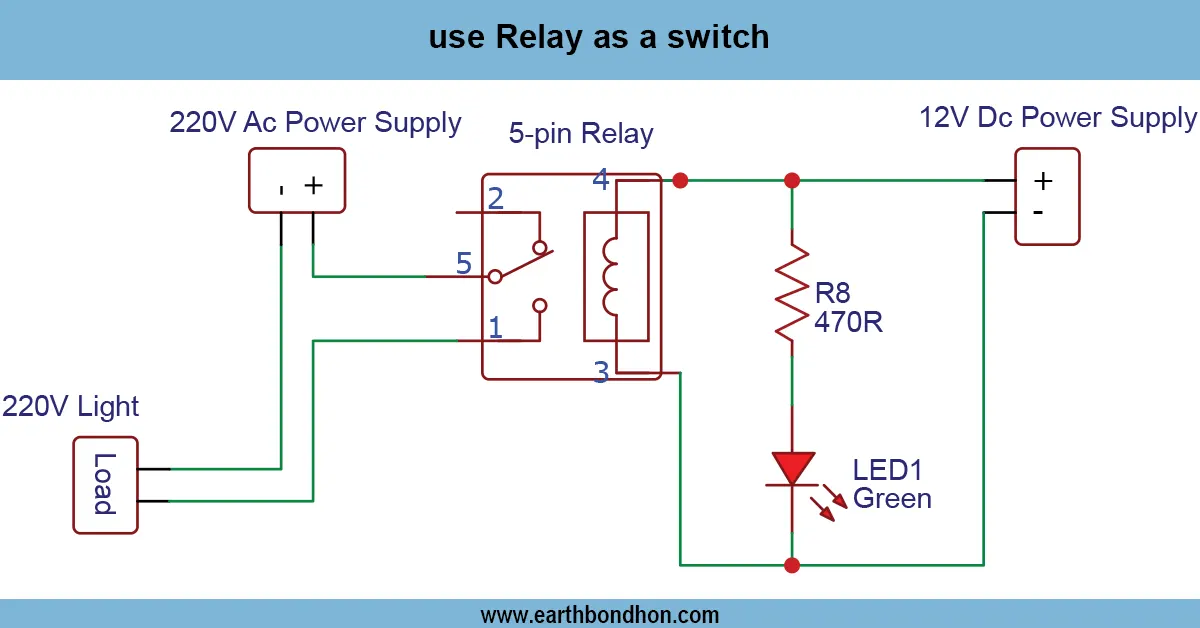
The DC Motor Control Forward, Reverse and Stop Using Relay is a cost-effective and easy way of operating the direction and functioning of a DC motor. Switches in polarity of the motor supply are carried out by relays to obtain forward and reverse motion. The third relay or logic set could be applied to safely stop the motor.
The circuit generally comprises DPDT ( Double Pole Double Throw ) relays to make forward and reverse exchange. The relays are acted upon by push buttons or toggle switches, which regulate the direction of the motors. It does not require a sophisticated electronic circuit and is appropriate for small robotics, automated doors, and home motor projects. It is not too complicated, it is cheap, and it provides practical learning of relay switching, polarity control of the motor, and simple automation. Higher currents may also be used to drive the motor by way of relays without straining small transistors or MOSFETs.
Work / Installation (Inputs → Outputs)
- Input → DC motor supply voltage (based on motor rating).
- Relays → DPDT relays switch motor polarity for forward and reverse motion.
- Control Switches / Buttons → Trigger relays for forward, reverse, or stop.
- Output → Motor rotates forward, backward, or stops depending on activated relays.
- Installation → Mount relays on PCB or perfboard; connect push buttons, ensure proper polarity, and place flyback diodes across relay coils for protection.
Testing & Final Adjustments
Once the circuit has been assembled, power up the circuit and test forward motion by pressing the forward button. Check reverse action by pushing the reverse button. Press to stop; this makes certain that the motor runs after stopping. Relay connections and polarity. Pay attention to check the relay connection and polarity to prevent short circuits. Apply flyback diodes to avoid spikes of voltage across the relay coils. Test under light load and moderate load to make sure that the relays change correctly and that the motor works without any problems. Modify wiring or switch in case the motor does not act as expected. It should be installed properly to guarantee the correct forward, reverse, and stop, nd so it is the best option to use on small automation, robotics, or educational projects.