

Simple Ultrasonic Humidifier
Build a simple ultrasonic humidifier using a 2SC6144 transistor for mist generation. Ideal for DIY electronics projects, home use, and small-scale humidification.

DIY ultrasonic mist generator:
An inexpensive ultrasonic humidifier based on 2SC6144 is an electrical device that transforms electrical signals into ultrasonic vibrations generated as a fine mist. The ultrasonic transducer is driven by the 2SC6144 transistor to generate the mist stably and efficiently.
low-voltage ultrasonic humidifier:
Simple Ultrasonic Humidifier with 2SC6144 is a circuit that is easy to build and uses a 2SC6144 to produce a fine mist to humidify the air. Those ultrasonic transducer uses 2SC6144 transistor as a high-frequency driver to convert an electrical signal into an ultrasonic vibration. These vibrations cause minute drops of water that appear in the form of a mist. This is the ideal project for hobbyists, students, and DIY electronics fanatics who are interested in knowing more about ultrasonic and transistor-based high-frequency driving. The circuit is low-voltage DC, and, therefore, safe to use inside the house. It is a PCB or breadboard-mountable assembly that can be used in small-sized water containers. The frequency of oscillation is determined by the components, including resistors and capacitors, which influence the mist density and stability. The design is simple and offers an economical, safe, and useful ultrasonic humidifier system that can be installed at home or used in the education sector or small-scale DIY projects.
⚡ Work & Installation (Input → Output):
- Power Supply → 12V DC (low-voltage, safe).
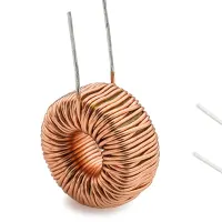
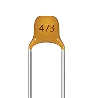
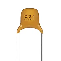
- Oscillator Circuit → Generates high-frequency signal for ultrasonic transducer.
- 2SC6144 Transistor → Amplifies and drives the transducer.
- Ultrasonic Transducer → Converts electrical signal into ultrasonic vibrations.
- Water Container → Mist is formed above water surface.
- Installation → Connect all components on PCB/breadboard, mount transducer above water, power ON, and adjust component values for optimal mist density.
Testing & Final Adjustments:
The circuit can be powered after assembly, and it should be determined whether mist is produced. When the mist is sparse, then change the values of the resistors or capacitors in the oscillator circuit to adjust the frequency. When used continuously, be sure to ensure that the transistor 2SC6144 is heat-sinked. Check that the ultrasonic transducer is positioned properly in the water in order to prevent damage. Check the device in several minutes to make sure that it works steadily and does not overheat. Safe boxes should be locked up to avoid interaction of water with electronics. Efficient, stable, and safe testing will ensure an efficient, safe, and effective DIY ultrasonic humidifier that could be used in homes, small-scale indoor projects, and learning electronics.


