
Automatic Street Light Circuit
Build an automatic street light circuit using a BT136 triac. Lights turn on at dusk and off at dawn using an LDR sensor for energy-efficient operation.

BT136 automatic street light circuit
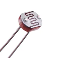
BT136 is an automatic street light circuit that switches on the lamps when the sun goes down and switches off when the sun comes up. The LDR detects the surrounding lig, nd drives the triac switch, removes the manual operation, and conserves power.
BT136 AC light controller
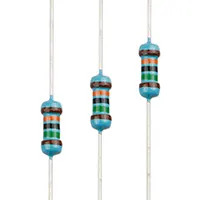
Automatic Street Light Circuit with BT136 Triac is a design of a circuit that automatically switches on street lights at night and off in the daytime. The circuit also incorporates the use of an LDR (Light Dependent Resistor) to measure the intensity of ambient light. Under sunlight, the LDR detects the sun, turns the triac off, and the lamp is turned off, which is the daytime. As the dusk continues, the LDR resistance increases, causing the BT136 triac to turn on and the lamp to light. The BT136 triac is a high-current AC switch that is appropriate in the case of lighting 220 V AC lamps without mechanical relays. The circuit is a convenient, economical, and safe street light, garden light, or even pathway light. It does not need a lot of parts, and only a handful of components (BT136, diac, resistors, capacitors, and LDR) are needed to construct and maintain.
Work / Installation (Inputs → Outputs)
- AC Input (220V) powers the circuit.
- LDR sensor with resistor network senses day/night light.
- Triggering diac & BT136 triac switch the AC load.
- Lamp Output turns on automatically at night and off during the day.
- Mount LDR facing open sky to detect sunlight accurately.
Testing & Final Adjustments
Connect the power supply and AC lamp after connecting them. Check in the daytime to make sure that the lamp is off. Darken the LDR, and the lamp is expected to turn on. Use the LDR series resistor to alter the value of the light sensitivity threshold in case it switches too soon or too late. AC connections should be well insulated to avoid shocks. The lamps of high watts should have a heat sink attached to BT136 or the snubber circuit to avoid voltage spikes. Ensure that switching is not done with flickering. When stable, the circuit is mounted in a waterproof case to be fitted outside. Periodically monitor the LDR and connections for the accumulation of dust or water.