
Voltage Regulator using Transistor
Build a high-current voltage regulator using transistors for a stable DC output, adjustable or fixed, suitable for motors, LEDs, and electronics projects.

Adjustable transistor regulator:
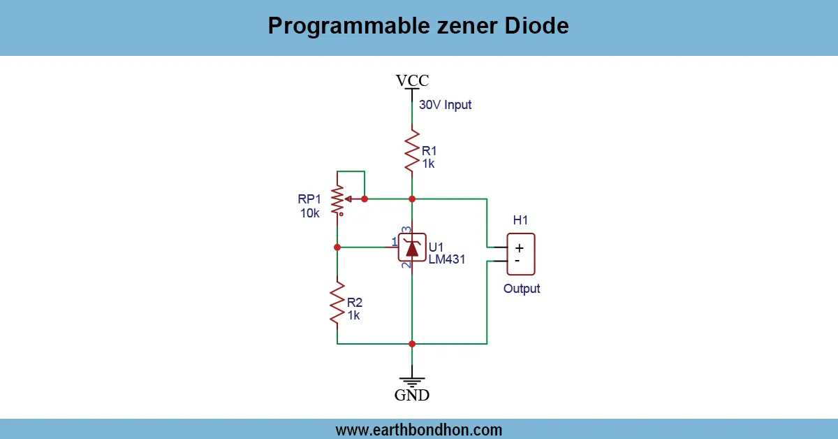
Another simple and cost-effective solution to supplying electronics and motors and other projects with stable DC voltage is a voltage regulator based on a transistor. The transistor is a variable resistor or pass element that ensures that the load voltage remains constant even with changes in the input voltage. The output may be fixed or variable using a potentiometer, zener diode ,or voltage reference. Input and output capacitors enhance stability in the voltage and minimise ripple. The design of this linear regulator was designed to drive bigger currents than most IC regulators when used with power transistors and heatsinks, hence it fits well with hobbyists, DIY hobbyists and electronics lab applications that need a dependable and reliable DC power supply.
Regulated DC power circuit:
A voltage regulator based on transistors is an easy to use and efficient way to provide a stable DC voltage to an electronics project, a motor, LEDs and even in the laboratory. The transistor in this circuit is a pass element that regulates the voltage over the load to supply a constant output with changes in the voltage input or the current in the load. A voltage reference or zener diode determines the target output voltage, and in designs that are adjustable, a potentiometer can be added to provide subtle fine control. The input and input capacitors are used to stabilize the voltage as well as minimize the ripple to provide continuous DC to delicate electronics. Large current applications usually need heatsinks to stop overheating of the transistor. Elective current-limiting circuits are useful in protecting the regulator and the devices connected to it against overcurrent. This kind of regulator has many applications in amateur electronics, hobbies, and laboratories. A transistor based voltage regulator has the capability of providing reliable, accurate, and safe DC power with proper assembly, wiring, and testing, so it can be used in both fixed and adjustable voltage applications.
⚡ Work & Installation (Input → Output):
The transistor voltage regulator is implemented by regulating the voltage drop across the transistor, which is a pass element. The output voltage is fixed to a voltage reference by a zener diode or voltmeter and fine adjustment provided by a potentiometer in adjustable designs. Voltage is made constant and ripple is minimized using input and output capacitors. Installation is done by connecting the input DC source to the collector (in NPN) or emitter (in PNP), the load to the transistor output and control circuitry to the base. Greater current applications may need heatsinks. The regulator and the load are safeguarded by optional current-limiting circuits. Correct wiring, polarity, and safe soldering are all that is needed to make sure that it operates safely. This regulator is a compact and reliable high-current regulator based on transistors that may be used to power motors, LED lights, microcontrollers, and other electronics that need regulated DC power.
Testing & Final Adjustments:
Once the transistor voltage regulator circuit has been assembled, it should be connected to an appropriate DC input voltag,e and the voltage across the resistoshould be r measured using a multimeter. Regulate the potentiometer, where it is present, until the required output voltage is obtained. Regulator Test the regulator with a dummy resistive load to avoid damaging delicate electronics. Care: The transistor must have a good heatsink itocarry large currents. Ensure that the input and the output capacitors are properly connected to minimize ripple and stabilize. In case of the current-limiting property of the circuit, test it under loading. Measure the temperature of the transistor, the output voltage, and current. Optimize the network ofpotentiometersr oresistorsor to get the correct voltage out. On confirmation, the transistor voltage regulator offers a stable, varia,ble or constant DC supply to motors, LEDs, microcontrol,lers and other electronic devices. Correct assembly and testing would guarantee durability, performance stab,ility and safety over DIY and laboratory applications.