

12v Dc motor speed control circuit
Build a 12V DC fan speed controller using BC557 PWM circuit. Adjust fan speed smoothly with the MOSFET driver. Simple, low-cost, and efficient design.

12V DC fan speed controller
A 12V DC fan speed controller is another simple PWM circuit that is used to control the airflow by varying the duty cycle. With a MOSFET and a 555 timer IC, you can create a cheap but efficient computer or cooling fan controller that will provide variable speed with reasonable power dissipation.
PWM DC fan controller circuit
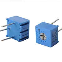
A 12V DC fan speed controller allows you to control the flow of a fan without any wastage of power. The circuit then regulates the length of time that the fan is fed in every cycle using PWM (Pulse Width Modulation). This varies the speed of the fan to be fast or slow, according to the duty cycle. The most common one is to implement a 555 Timer IC in the astable multivibrator mode, which produces a PWM signal. The PWM drives a MOSFET, which is an electronic switch to control the fan. The duty cycle can be adjusted with the help of a potentiometer, and this enables the variable speed. This process is much more effective than the process of resistor-based controllers, as it does not produce heat losses. The circuit is very executable in 12V DC fans employed in computers, car cooling, or small appliances. With the potentiometer, it is possible to have a silent, low-speed operation with full power when needed. It has a simple design, is inexpensive, and dependable when it comes to DIY projects.
Work / Installation (Inputs → Outputs)
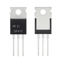
The input is a 12V DC power source, which is connected directly to the fan and the circuit. The potentiometer-controlled 555 timer IC produces a PWM signal. This PWM is used to power the MOSFET, which alternates the fan ON and OFF at high frequency. Through a modification in the duty cycle, the fan speed is modified. The positive terminal of the fan is directly connected to the +12V supply, and the negative terminal of the fan goes through the MOSFET. Across the fan is a diode used to absorb back-EMF. The result is the production of a variable-speed fan with less power consumption and a smooth performance.
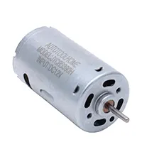
Testing & Final Adjustments
And then, having built the circuit, a load must be connected in the form of a 12V DC fan. Rotate the potentiometer slowly and monitor fan speeds. When the duty cycle is low, the fan must rotate slowly and quietly, whereas at high duty cycles, the fan must attain full speed. Test MOSFET; make sure it does not get hot, and apply a heatsink. Make sure that the fan moves without jolting. Make sure that the diode that is over the fan is properly positioned, so that the MOSFET is not exposed to spikes of back-EMFs. When the fan is not started when using very low duty cycles, it is better to slightly raise the minimum PWM so that the fan can start smoothly. Measure the current consumption at varying speeds to ensure efficiency. When the performance becomes stable, then cover the circuit with a plastic box. Optimization of fan response can be carried out at the end, as well as in cases where it is utilized in a computer or battery-operated system, where efficiency is paramount. This provides a sure, noiseless, and durable speed control of fans.


