Creators
Rojony Khatun Author
Rojony Khatun
CalculatorToolsProjectExpert
Reviewers
Małgorzata Koperska, MD Steven Wooding
Last updated: January 14, 2026

18650 Battery Charger Voltage Protector Circuit Using TL431

🇺🇸
English
Default
🇪🇸
Español
Spanish
🇫🇷
Français
French
🇩🇪
Deutsch
German
TL431 Transistor

TL431 Adjustable Shunt Regulator

Precision programmable shunt regulator, works like an adjustable Zener diode (2.5V–36V)

BD140 Transistor

BD140 Transistor

PNP medium power transistor, collector current up to 1.5A, voltage up to 80V

BC548B Transistor

BC548B Transistor

NPN general-purpose low noise transistor, hFE range 200–450, collector current up to 100mA

3V LED 5mm

3V LED 5mm

3V, 5mm round light-emitting diode

1K Fixed Resistor 1/4W

1K Fixed Resistor 1/4W

A 1,000-ohm resistor rated for 0.25 watts

4.7R Fixed Resistor 2W

4.7R Fixed Resistor 2W

A 4.7-ohm resistor rated for 2 watts

20K Fixed Resistor

20K Variable Resistor

Adjustable resistor with 20,000 ohm resistance

680-ohm Fixed Resistor 1/4W

680R Fixed Resistor 1/4W

A 680-ohm resistor rated for 0.25 watts

*Please note: These are affiliate links. I may make a commission if you buy the components through these links. I would appreciate your support in this way!

18650ma Battery charger Voltage Protector Circuit

Build a 18650 battery charger with voltage protection using TL431. Ensures safe charging, prevents overcharge, and extends battery life.

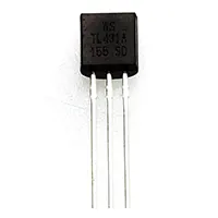
TL431 voltage protector for 18650

The battery charger will have a 18650 battery with TL431 voltage protection to ensure safe charging that will terminate at 4.2 V and prevent overcharging to prolong the battery life.

simple overcurrent protection circuit

A short-circuit overcurrent protection circuit is an important safety measure in electronics and electrical systems to ensure the safety of the equipment in case of overcurrent flow. This circuit detects the overcurrent when a short circuit or momentary explosion happens and cuts the power to the load to prevent failure of components, fire hazards, or damage to power sources.

Fuses, circuit breakers, or electronic components MOSFETs and current sensors, may be used as the overcurrent protection circuit. Current-sensing resistors, comparators, and relays or transistors are commonly used in modern DIY circuits and are used to reduce instantaneous load in the circuit when the current rises beyond a safe operational value. This guide will discuss the constituents, working principle, circuit diagramstep-by-stepep construction, as well as trip advice to construct a highly reliable short-circuit overcurrent protection system to be used in AC and DC applications.

Importance of Overcurrent Protection in Circuits

  • Protects Devices: Prevents damage to sensitive electronics and appliances.
  • Prevents Fire Hazards: Avoids overheating of wires and components.
  • Improves Reliability: Ensures stable operation of power systems.
  • Enhances Safety: Protects users from electrical risks.
  • Supports Longevity: Extends circuit and power source lifespan.

Components Required for DIY Circuit

Component Quantity Purpose
Fuse or Circuit Breaker1Initial protection for high current
Current Sensing Resistor (Shunt)1Detects overcurrent
Operational Amplifier / Comparator1Compares sensed current with reference
MOSFET or Relay1Switches load ON/OFF
Resistors2–5Biasing and voltage division
Capacitor1Filtering and stability
Power Supply1Powers the circuit
LED Indicator1Shows overcurrent status
PCB / Breadboard1Assembly platform

Working Principle of Overcurrent Protection

1. Current Sensing

The shunt resistor measures load current through the voltage drop across it.

2. Comparison Stage

A comparator compares the sensed voltage with a reference representing the maximum safe current.

3. Load Disconnect

If the current exceeds the threshold, the comparator triggers a MOSFET or relay to disconnect the load.

4. Indicator LED

The LED turns on to indicate a fault/overcurrent condition.

5. Reset & Recovery

After clearing the fault, the system can reset automatically or manually.

Circuit Diagram Explanation

  • Shunt Resistor: Placed in series with the load for current sensing.
  • Comparator Input: One input receives shunt voltage; the other receives reference voltage.
  • Comparator Output: Drives MOSFET gate or relay coil to disconnect the load.
  • LED Indicator: Shows fault conditions through comparator output.
  • Power Supply: Powers comparator and switching device.

Step-by-Step Construction Guide

  1. Place a shunt resistor in series with the load and connect its voltage drop to the comparator.
  2. Set reference voltage according to the desired maximum safe current.
  3. Connect the MOSFET or relay so that the comparator output controls the load.
  4. Add an LED with a resistor to show fault indication.
  5. Test circuit with normal and overcurrent conditions and adjust threshold if needed.

Applications of Overcurrent Protection Circuits

  • Power supplies (AC/DC)
  • Battery chargers and inverters
  • Motors and industrial loads
  • Home appliances
  • DIY electronics projects

Troubleshooting Tips

  • Load not disconnecting → Check comparator reference voltage and wiring.
  • MOSFET/relay not switching → Ensure proper gate/base drive voltage.
  • False triggering → Add a filtering capacitor to comparator input.
  • LED not lighting → Verify resistor value and polarity.
  • Circuit not powering → Check supply voltage and connection polarity.

Frequently Asked Questions - 18650ma Battery charger Voltage Protector Circuit:

Why use TL431 in a charger?

It provides precise voltage reference for cutoff at 4.2V.

What is the cutoff voltage for 18650?

4.2V per cell is the safe charging limit.

Can TL431 replace a BMS?

For single cells, yes. For multiple cells, use a BMS.

Does it protect from overcurrent?

No, it mainly protects against overvoltage.

What input voltage is required?

5V to 12V DC depending on regulator used.

Is it safe for lithium batteries?

Yes, it ensures safe charging by preventing overcharge.

Can I charge multiple 18650 cells?

Not directly. Each cell needs individual protection.

What is TL431?

It is a programmable shunt voltage reference IC.

How much current can it handle?

It handles small current; a transistor/relay is needed for higher loads.

Can I use LED indicator?

Yes, LED can be added for charging and full status.

Comments

Please login to comment.

Rojony Khatun

Rojony Khatun

Calculator Tools Project

Rojony Khatun is the creator of a free online tools website designed to simplify everyday and engineering-related calculations for students, professionals, and hobbyists. The platform offers a wide variety of basic and advanced calculators across key categories, including Electrical Calculators, Electronic Calculators, and Time & Date Calculators, helping users solve problems quickly and accurately.