How to Make 1-30V 0-10A Regulated Variable Power Supply Circuit
Build a 1-30V 0-10A regulated variable power supply. Step-by-step DIY guide with components, circuit diagram, working principle, and applications for electronics projects.

High current adjustable DC power supply
One of the most useful DIY electronic projects is a 1-30V 0-10A regulated variable power supply circuit. It is a consistent, variable DC output that may be employed in testing and driving diverse electronic circuits and motors, and LEDs or other apparatuses.
Adjustable voltage and current supply
This power supply can adjust its voltage within the range of 1V to 30V, and the current limit is 10A. It generally operates on the principle of reducing the voltage on AC mains using a transformer, changing AC to DC using a bridge rectifier, removing ripples using filtering capacitors, a nd offering a stable yet adjustable output with a voltage regulator IC (such as LM338). There are also additional current-limiting and protection circuits, which are used to guarantee safe operation even when under load.
This manual covers all parts, mechanisms, circuit diagrams, and assembly instructions of a high-current, variable power supply using a respirator, controlled by a power supply, and regulated.
Key Features and Advantages
- Adjustable voltage from 1V to 30V
- Maximum output current up to 10A
- Stable and regulated output with low ripple
- Short-circuit and overcurrent protection
- Ideal for electronics testing, charging batteries, and DIY projects
Components Required for Variable Power Supply
- Transformer (AC 0–30V, 10A)
- Bridge Rectifier (10A diodes or module)
- Filter Capacitors (4700μF–10000μF, 50V)
- Voltage Regulator IC (LM338 for high current)
- Resistors for voltage adjustment
- Potentiometer (for adjustable voltage)
- Heat sink for regulator IC
- Fuse (10A–15A)
- Wires, PCB, or aluminum chassis for assembly
- Cooling fan (optional for high current operation)
Working Principle
Transformer and Rectification
AC mains voltage is stepped down by the transformer to 0–30V AC. The bridge rectifier then converts this AC to DC.
Filtering and Smoothing
Large electrolytic capacitors smooth the DC signal and reduce ripple, ensuring stable input to the regulator.
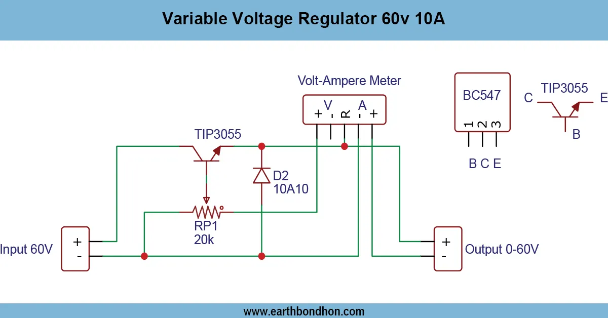
Voltage Regulation using LM317 / LM338
The LM338 provides adjustable voltage output that can be modified using a potentiometer connected to its adjust pin.
Current Limiting Circuit
An adjustable current limiter prevents the load from exceeding 10A, protecting devices from overcurrent damage.
Protection Features
Fuses and thermal protection in the LM338 safeguard the circuit from excessive heat and short circuits.
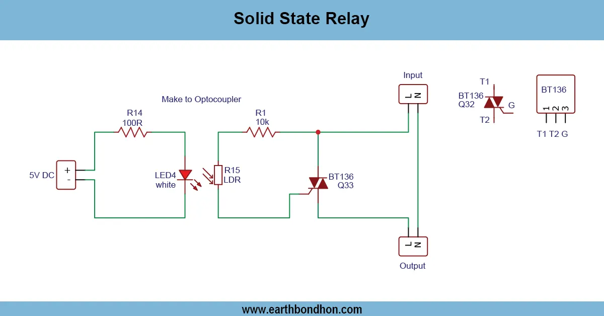
Circuit Diagram of 1–30V 0–10A Power Supply
- Connect AC mains to transformer primary
- Step-down AC is rectified using bridge rectifier
- Filter capacitors smooth the DC signal
- Connect LM338 with adjustment potentiometer
- Add series resistors for current sensing
- Connect output terminals and LED indicator
- Install fuse and heatsink
Step-by-Step Construction Guide
- Mount transformer and wire the primary/secondary connections
- Assemble bridge rectifier and connect filter capacitors
- Install LM338 on a heatsink
- Connect input, output, and adjust pins
- Add potentiometer for voltage adjustment
- Install fuse and current limiting resistors
- Test output with low load
- Adjust voltage and monitor current
Applications of Variable Power Supply
- Powering DC motors and electronic circuits
- Charging batteries of various voltages
- Testing DIY electronics projects
- Laboratory and workshop use
- LED testing and prototyping
Safety Precautions
- Use insulated wires suitable for high current
- Ensure proper heatsinking of LM338
- Never short-circuit the output
- Always use the correct fuse rating
- Start testing at low voltage
Troubleshooting Common Issues
No Output or Low Output
Check transformer secondary voltage and verify rectifier and LM338 connections.
Overheating of Regulator
Use a proper heatsink and optional cooling fan. Lower continuous load if needed.
Ripple or Noise in Output
Check filter capacitors and add more decoupling if required.