
fix 3-3v Voltage Regulator
Regulate DC voltage to a stable 3.3V using the KIA78D33AF IC. Ideal for microcontrollers, sensors, and low-voltage electronics projects.

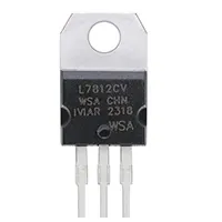
3.3V voltage regulator KIA78D33AF
The KIA78D33AF is used as a fixed 3.3V voltage regulator to avoid the fluctuation of DC power to microcontrollers, sensors, and low-voltage electronics. It has thermal protection and easy voltage regulation.
KIA78D33AF regulator circuit
The Fixed 3.3V Voltage Regulator with KIA78D33AF gives an easy and consistent way of providing constant 3.3V DC power to an electronics circuit. This IC is considered to provide constant voltage output and internal thermal and overload protection. It is widely found in powering microcontrollers, sensors, logic ICs, and low-voltage electronics projects in which a more accurate 3.3V supply is necessary. To be properly regulated, the input voltage is supposed to be greater than 3.3V (usually 5-15V DC). The input and the output are typically added with external capacitors to enhance stability and lessen the voltage ripple. It is simple to build a small, economical circuit, which is why the circuit is suitable for DIY electronics, projects with hobbies, and embedded systems. Higher current loads may be heatsinked.
Work / Installation (Inputs → Outputs)
- Input Voltage → DC 5–15V supply.
- KIA78D33AF IC → Regulates input to a stable 3.3V.
- Input Capacitor (C1) → Smooths input voltage fluctuations.
- Output Capacitor (C2) → Reduces voltage ripple and stabilizes output.
- Output → 3.3V DC for powering devices.
- Installation → Place IC on PCB; connect input/output capacitors; optionally add heatsink for high current applications.
Testing & Final Adjustments
Once assembled, add DC input voltage and read the output using the multimeter. Make sure that the voltage of the output is stable at 3.3V. Capacitors and IC pins Polarity. Load test with a small microcontroller or LED to check that there is no change in voltage. Watch for overheating of the IC; add a heatsink if needed. Check with good variations of input voltage within the recommended range. Change the adjustments of capacitors when the voltage ripple is large. Adequate testing will also guarantee the reliability and safety of the operation of microcontrollers, sensors, and other low-voltage electronics circuits.
Frequently Asked Questions - fix 3-3v Voltage Regulator:
What is KIA78D33AF?
It is a fixed 3.3V voltage regulator IC with thermal and overload protection.
What input voltage is needed?
Typically 5–15V DC, higher than 3.3V for proper regulation.
Can it power microcontrollers?
Yes, ideal for 3.3V microcontrollers and low-voltage devices.
Are capacitors required?
Yes, input and output capacitors improve stability and reduce ripple.
Do I need a heatsink?
Optional for low current; required if output current is high.
Is it beginner-friendly?
Yes, simple IC-based circuit suitable for hobby projects.
Can it replace batteries?
No, it regulates DC voltage; batteries supply the input DC.
What current can it supply?
Depends on IC specs, typically up to 1–1.5A with heatsink.
Is it cost-effective?
Yes, inexpensive and widely available IC for 3.3V regulation.
Can it be used in sensors?
Yes, provides stable voltage required for precise sensor operation.