
Voltage Regulator using IRFZ44N Mosfet
Build a high-current voltage regulator using an IRFZ44N MOSFET for a stable and adjustable DC output, suitable for motors, LEDs, and DIY electronics projects.

IRFZ44N voltage regulator:
A voltage regulator based on the IRFZ44N MOSFET is an adjustable DC regulator with high current, which finds use in electronics, motors, LEDs, and laboratory applications. IRFZ44N is a pass transistor that is made up of a potentiometer or control circuit that limits the voltage and enables the voltage to be adjusted smoothly and precisely. Input and output capacitors provide a stable voltage and minimise ripple, and a heatsink ensures that the device can operate safely at high currents. The design featuring MOSFETs is capable of delivering higher current loads than standard IC-based design regulators, making it the choice of hobbyists, DIYers ,and electronics laboratory applications that would like adjustable, reliable, and high current DC power.
Adjustable DC supply IRFZ44N:
An adjustable DC power supply with high current is offered with a voltage regulator based on the IRFZ44N MOSFET that is applicable to electronics projects, motors, LEDs, and lab use. The IRFZ44N is a pass transistor, which regulates the output voltage by a potentiometer or control circuit, and thus, the voltage adjustment is very fine and smooth. Spurring voltage spikes and minimizing ripple, input and output capacitors provide stable and clean DC power to sensitive equipment. The IRFZ44N, as opposed to regular IC regulators, is able to operate with higher currents and, therefore, is best suited to high-power applications. Heatsinks are necessary to cool down the system when there is high power consumption and to avoid thermal abort. Both the regulator and the devices connected to it may be overloaded, and optional current-limiting circuits may prevent this. It is a small and inexpensive MOSFET-based regulator that can be used by hobbyists, electronics laboratories, and DIY builders. The IRFZ44N voltage regulator, when assembled, wire, and tested correctly, is a reliable, stable, adjustable, and safe DC power supply, a safe and reusable high-current source, in a number of electronics applications and experimental systems.
⚡ Work & Installation (Input → Output):
The IRFZ44N voltage regulator works through regulating the voltage drop across the MOSFET which is a variable resistor. The MOSFET is adjusted by a potentiometer or control circuit which is connected on the gate enabling the output voltage to be controlled very accurately. Stability is enhanced and voltage ripple is minimized by the use of input and output capacitors. To install, one has to connect the input DC source to the drain side of the MOSFET and the load to the output side of the MOSFET and the control circuitry to the gate. Designs with high-currents must incorporate a heatsink to cool off and prevent thermal shutdown. Elective current-limiting will guard the regulator and other devices to which it is connected. Wiring, insulation and polarity are taken care of to make sure that it works well. This controller has a stable DC supply of up to 1000 mA and can be used to power motors, LEDs, microcontrollers, and other high-current electronics.
Testing & Final Adjustments:
Following the assembly of IRFZ44N voltage regulator, connect it to the DC input voltage in the circuit within the rated value. Connection A multimeter is used to monitor the output voltage and using the potentiometer, fine-tuning the voltage can be made. Firstly, test the regulator with just a dummy load that is resistive to prevent damaging delicate electronic parts. MOSFET should be adequately heatsinked to be used safely with large currents. Ensure that input and output capacitors are fitted with correct installation to reduce voltage ripple. In case the regulator has current-limiting circuitry, ensure that it works under load. Measure temperature, output voltage and current. Adjustment of fine-tuning of potentiometer and resistor values to give fine voltages. After testing, IRFZ44N MOSFET voltage regulator is a fine and reliable adjustable high-current DC source of motors, LEDs, microcontrollers, and other electronics. The correct assembly guarantees the stable operation, long-term stability and safe operation, therefore it could be adapted to DIY electronics projects, learning laboratories, and professional work that needs high-current regulated DC power.
Frequently Asked Questions - Voltage Regulator using IRFZ44N Mosfet:
What is an IRFZ44N voltage regulator?
A high-current adjustable DC regulator using IRFZ44N MOSFET.
What voltage range can it provide?
Depends on input voltage and circuit design; typically adjustable.
Which components are required?
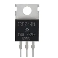
IRFZ44N MOSFET, potentiometer, resistors, capacitors, DC source, heatsink.
How do I adjust the output voltage?
By turning the potentiometer controlling the MOSFET gate voltage.
Do I need a heatsink?
Yes, for safe high-current operation.
Can it supply high current?
Yes, suitable for motors, LEDs, and electronics circuits.
Is it suitable for DIY projects?
Yes, widely used in hobby electronics and lab setups.
Can I add current limiting?
Yes, optional circuits can protect supply and load.
Can it power sensitive electronics?
Yes, with proper filtering and voltage adjustment.
Is it reliable for long-term use?
Yes, if assembled with heatsinking, correct wiring, and stable components.