
DC Motor Control Circuit
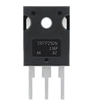
Control DC motor speed and direction using IRFP250N MOSFET. Simple H-bridge or PWM-based circuit for reliable low to medium power motor applications.

MOSFET motor control DIY
IRFP250N DC Motor Control Circuit offers accurate control in the speed and direction of the motor. IRFP250N is a high-current N-channel MOSFET that can be used to operate moderate DC motor loads effectively. This circuit can be used to control an H-bridge to control a motor in both directions or to control the speed by using PWM (Pulse Width Modulation). The PWM signal or logic inputs can be varied, thus causing the motor to rotate clockwise or counterclockwise at variable speeds. It is advisable to use proper gate resistors, flyback diodes, and heat sinks to inhibit the MOSFET and to make the operation of the circuit proceed smoothly.
The project can apply to hobby robotics, automated systems, and small machinery. It includes practical education on MOSFET switches, H-bridges, and PWM speed control. The circuit is inexpensive, dependable, and can be carried out on a PCB or breadboard when running an experiment.
IRFP250N transistor motor control
DC motor control circuit with IRFP250N permits control of speed and direction as a variable. The motor can be used to move forward and reverse as well as at controllable speeds using the H-bridge and PWM methods.
Work / Installation (Inputs → Outputs)
- Power Input → DC motor supply voltage (depends on motor rating).
- IRFP250N MOSFETs → Act as high-current switches for motor terminals.
- H-Bridge / PWM Control → Determines direction and speed of the motor.
- Protection Components → Flyback diodes to prevent voltage spikes, resistors for gate control.
- Output → Motor rotates clockwise or counterclockwise at controlled speed.
- Installation → Mount on PCB or heatsinked breadboard; ensure proper MOSFET orientation and gate drive signals.
Testing & Final Adjustments
Once the circuit has been assembled, connect the DC motor and provide the supply voltage. Test PWM input and test H-bridge logic. To test H-bridge logic, the H-bridge needs to be rotating forward/reverse. Measure the voltage across the motor terminals to ascertain good switching of the MOSFET. Regulate PWM duty cycle to control motor speed. Make sure that flyback diodes are installed properly to avoid the inductive spike damage. Make sure that MOSFETs are not overheating; attach heatsinks when needed. Test under different load conditions to ensure that it works well and in a stable manner. When verified, the circuit may be wired in permanently to be used in robotics or automation. Adequate calibration provides the ease of varying speed and protective directional control.