


Adjustable Voltage and current Regulator Circuit
Build an adjustable voltage and current regulator circuit using an IRFZ44N MOSFET for power supply, battery charging, and motor control applications.

adjustable voltage regulator using MOSFET
A variable regulator circuit with IRFZ44N regulates current and voltage, and is useful in battery charging and driving LEDs, and in DIY power supplies in the laboratory.
DC power supply with IRFZ44N
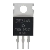
The IRFZ44N MOSFET is a high-power N-channel transistor that can be used to conduct high current, and this makes it suitable for constructing a programmable voltage and current regulator circuit. This form of regulator is common in DIY power supplies, battery charging, LED drivers, and DC motor control.
The principle of work is very straightforward: the IRFZ44N MOSFET is used as a series pass device, and the gate of the device is driven by a voltage reference circuit. The gate voltage may be tuned by varying a potentiometer, and this varies the output voltage applied to the load. To regulate it now, a shunt resistor and a comparator are connected to detect current flow and adjust it in case of a set point.
This renders the circuit flexible, efficient, and cheap as opposed to the linear regulators. The IRFZ44N can produce high current output with 12V24V DC loads with proper heat sinking and cooling.
Work / Installation (Inputs → Outputs)
- Input DC Source (12V–24V) supplied to MOSFET stage.
- Gate Drive Circuit with potentiometer adjusts output voltage.
- Shunt Resistor & Comparator regulate current flow.
- Output DC gives adjustable voltage & current to load.
Testing & Final Adjustments
Having connected the regulator circuit, connect it to a variable DC supply (1224V). The voltage control should be tested first by making the potentiometer rotate and reading the output using a multimeter. A resistive dummy load is next connected, and the current flow is monitored. Adjust the current potentiometer in the control to ensure that there is correct current limiting. Accurately series an ammeter. Note that the IRFZ44N MOSFET should be placed on a heat sink to withstand a high dissipation of power. Test with various loads, e.g,. DC motors or arrays of LEDs, to ensure that it runs at a steady load. In the case of overheating, increase cooling by using a fan, or check parallel MOSFETs. Last adjustments must be made to have a smooth regulation of the voltage and current without oscillation.
Frequently Asked Questions - Adjustable Voltage and current Regulator Circuit:
What is IRFZ44N used for?
It is used for voltage and current regulation, motor control, and battery chargers.
What is the max voltage input?
Typically 12V to 24V DC, depending on design.
How much current can it handle?
It can handle up to 50A with proper cooling.
Can I use it in power supplies?
Yes, it is widely used in DIY adjustable DC power supplies.
Does it need a heat sink?
Yes, a heat sink and fan are required for high loads.
Can it charge batteries?
Yes, it can regulate charging voltage and current.
What is the control method?
Voltage control via gate drive and current sensing resistor.
Is it better than LM317?
Yes, for high current applications it is more efficient.
Can it drive LED strips?
Yes, it works well as a constant current driver.
Is short-circuit protection included?
Yes, with shunt resistor and comparator.