


Running LED Chaser Light
Build a running LED chaser light using BC547 transistors. Create sequential LED effects for decorations, indicators, or DIY electronics projects easily.
running LED light DIY
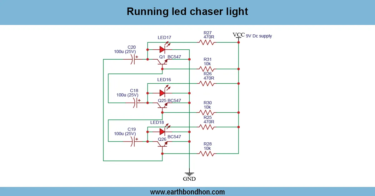
In a running loop, a chaser light with BC547 lights up the lights one after another. The transistors BC547 make LEDs light up and light down in rotation, generating a beautiful chasing effect.
simple LED sequence circuit
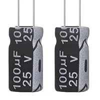
The Running LED Chaser Light with BC547 is a famous electronics project, which illuminates LEDs in a sequence to produce a chasing effect. Each of the LEDs would be controlled by a switch (BC547 transistor) to produce timing delays, usually using capacitors and resistors. The circuit is ideal for hobbyists, students, and DIY electronics enthusiasts who would like to develop an understanding of transistor switching, timing circuits, and sequential control. It can be supplied at low-voltage DC and will be safe, and is therefore suitable for breadboard assembly or in small PCB applications. The LEDs can be changed in accordance with your design needs. The effect of running LEDs would best be used in ornamental lighting, or indicators, or in learning practical electronics ideas. The selection of resistors and capacitors is good to provide stable operation and a steady speed of LED chasing.
Work / Installation (Inputs → Outputs)
- Power Supply → 5–12V DC for safe operation.
- Timing Components → Capacitors and resistors control LED sequence speed.
- BC547 Transistors → Act as switches to turn LEDs on and off sequentially.
- LEDs → Connect in series with transistors and resistors.
- Installation → Assemble on breadboard or PCB, connect LEDs, resistors, capacitors, and transistors, then power the circuit to see running effect.
Testing & Final Adjustments
Once it is assembled, power the circuit and note the sequence of LEDs. Modulate the speed of the LED chase by changing the values of the resistor or the capacitor. Always be sure that all the transistors of type BC547 are positioned properly (collector, base, emitter). Experiments: Add and remove stages to experiment with the number of LEDs to have and keep current limiting resistors. When it is properly tested, it will operate in a smooth manner in sequence without flickering or skipping. In cases of permanent construction, mounting parts on the PCB are to be used, and a heatsink may be required in case of prolonged operation. This is a good project to read about sequential control of transistors, timing circuits, and the use of LEDs in hobby electronics.