Hand Sanitizer Dispenser Diy Circuit
Build a touchless hand sanitizer dispenser DIY circuit using an IR sensor, a relay, and a pump. Step-by-step guide, components, working principle, and FAQs included.

What Is a Hand Sanitizer Dispenser DIY Circuit?
A hand sanitiser circuit DIY is an electronic system which dispenses liquid sanitiser on detection of human hands. It also substitutes manual pressing and enhances hygiene through direct contact avoidance.
homemade sanitizer dispenser electronics project
The DIY hand sanitiser dispenser is one of the practical electronics projects, and with the infrared (IR) technology, the project enables one to construct a touchless hand sanitiser dispenser. This system will identify hands close to the sensor and automatically turn on a small DC motor to squirt sanitiser.
The DIY circuit of the hand sanitiser dispenser is an IR sensor module to scan the presence of a hand, a signal amplifier or microcontroller to process, and a relay to adjust a miniature pump or motor. These dispensers are sanitary, do not cross-contaminate and are suitable either at home or in the office or even in the open. In assembling this project, you get to know about IR detection, relay control, motor driver and assembling a circuit that involves creating a useful health and safety device.
DIY Touchless Sanitizer Dispenser Circuit
Hands-free sanitizer dispensing using IR sensor, transistor, and relay — ideal for hygienic, low-power automation projects.
Advantages of a Touchless Sanitizer Dispenser
- Hygienic: Minimizes cross-contamination.
- Automatic Operation: Hands-free dispensing.
- Easy to Build: Uses simple components.
- Energy-Efficient: Low-power design.
- Educational: Learn sensor interfacing, relay driving, and fluid control.
Components Required
| Component | Quantity | Purpose |
|---|---|---|
| IR Sensor Module (TCRT5000 / HC-SR501 optional) | 1 | Detects hand presence |
| NPN Transistor (BC547 / 2N2222) | 1 | Amplifies sensor signal to drive relay |
| Relay Module (5V or 12V) | 1 | Switches sanitizer pump |
| DC Pump / Motor | 1 | Dispenses sanitizer |
| Resistors (1kΩ – 10kΩ) | Various | Biasing for sensor and transistor |
| Capacitors (10uF – 100uF) | Optional | Filtering and stabilization |
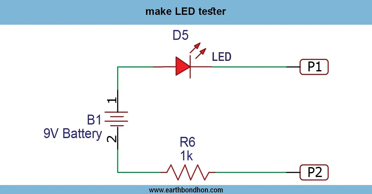
| LED Indicator | 1 | Shows system active |
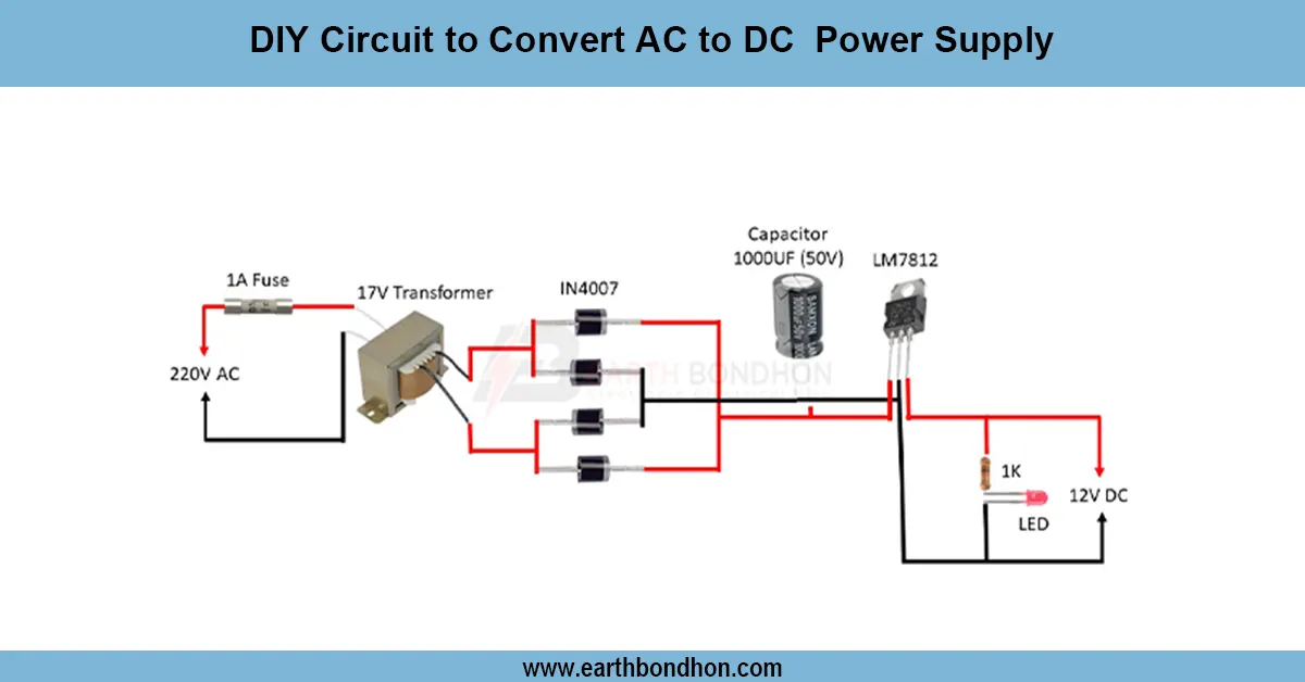
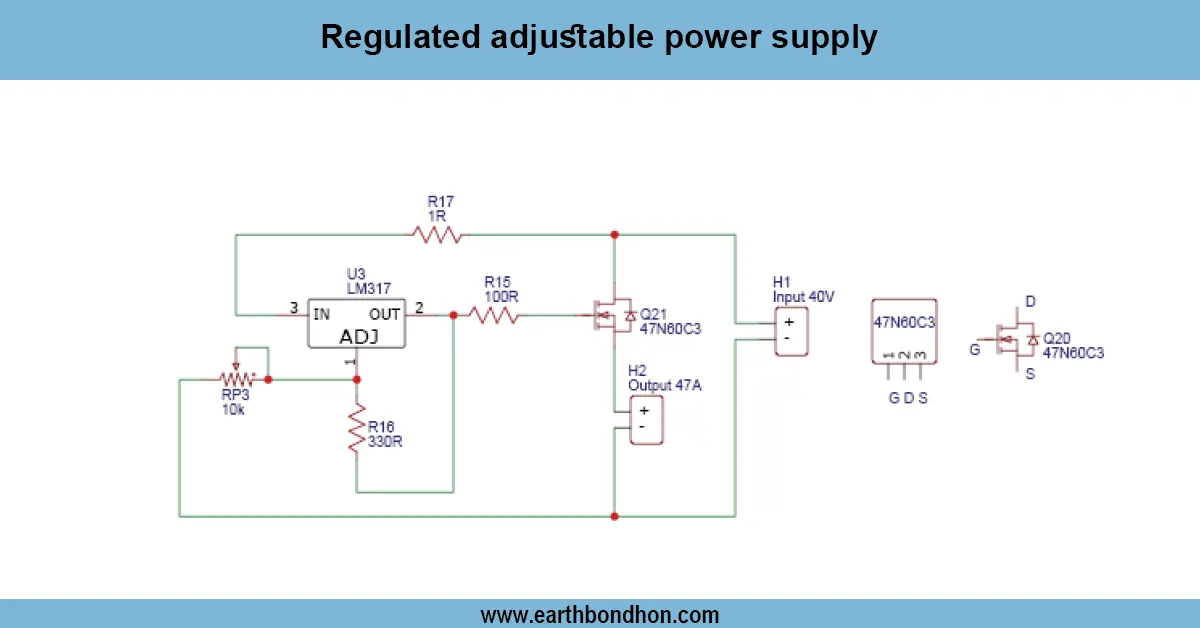
| Power Supply (5V–12V DC) | 1 | Powers sensor, relay, and pump |
| Enclosure | 1 | Mounts sensor, circuit, and pump |
Working Principle
IR Sensor Detection Stage: IR sensor emits light and detects reflection from a hand. Output goes HIGH or LOW based on presence.
Signal Amplification: Transistor amplifies the sensor signal to drive the relay. Microcontroller optional for advanced control.
Relay Switching Stage: Relay energizes the DC pump to dispense sanitizer; flyback diode protects against coil voltage spikes.
Pump Output: Pump dispenses sanitizer for a controlled duration and stops when hand is removed.
Power and LED Indicators: LED shows active status. Power supply provides regulated voltage for sensor, relay, and pump.
Circuit Diagram (Text)
IR Sensor OUT → Resistor → Transistor Base
Transistor Collector → Relay Coil
Transistor Emitter → GND
Relay Contacts → DC Pump Power Line
LED → Parallel to Relay Coil via Resistor
Power Supply → Powers sensor, relay, and pump
Step-by-Step Construction Guide
- Install IR sensor facing outward; connect VCC, GND, and OUT pins.
- Connect sensor output to transistor base through a resistor; emitter to ground, collector to relay coil.
- Wire relay coil with flyback diode; connect relay contacts to DC pump power line.
- Install LED in parallel to relay coil to indicate activation.
- Connect DC 5–12V power supply matching pump and relay ratings.
- Test by placing hand near sensor; adjust sensitivity as needed.
Applications
- Homes, offices, and hospitals
- Public sanitizing stations
- DIY automation projects
- School and laboratory hygiene systems
- Touchless public kiosks
Troubleshooting Tips
| Problem | Solution |
|---|---|
| Pump not activating | Check relay and transistor connections. |
| Sensor not detecting hands | Adjust IR sensor sensitivity or alignment. |
| LED not lighting | Check LED polarity and series resistor. |
| Pump running continuously | Check sensor output logic and transistor bias. |
| Power issues | Ensure supply voltage matches sensor, relay, and pump requirements. |