
5v Regulator 7805 Upgrade to 10a
Learn how to upgrade a 7805 voltage regulator to deliver up to 10A output using pass transistors or buck converters with safe installation steps.

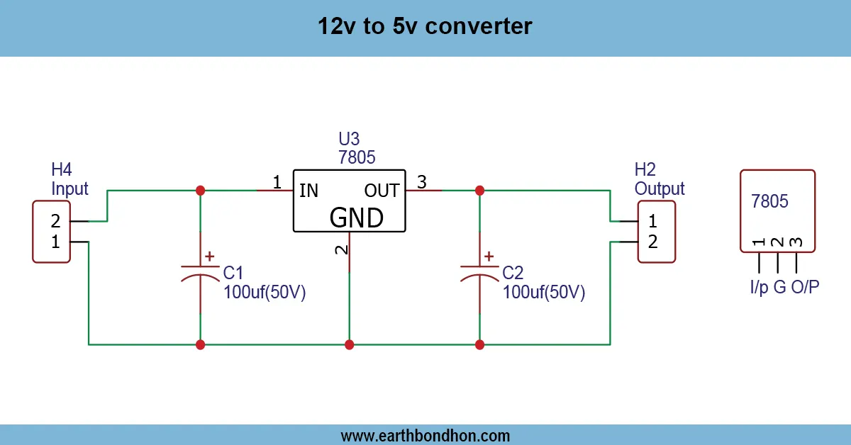
7805 10A regulator circuit
The 7805 voltage regulator is a common electronics component to stabilise 5V. Its current limiting range is, however, approximately 1A. Pass transistors can be added to the 7805 to boost it to 10A, or it can be substituted with a DC-DC buck converter. The regulator provides a voltage, but external parts increase current, hence it is applicable in high-power projects such as motors, microcontrollers, and LED systems.
5V 10A power supply using 7805
A regulator typically supplies up to 1A by a 7805 regulator, yet in a significant number of electronic projects, more current is needed. In order to turn a 7805 into a 10A, an external pass transistor, such as 2N3055 or a MOSFET, can be connected. The high voltage is regulated by the 7805, and the high current load is switched by the external transistor. With correct heatsinking and cooling, this can be run to 10A with a stable 5V output. The second effective alternative would be a switching buck converter, which is less heat-generating and more efficient. The Linear regulator with a booster transistor can be used to achieve a noise-free supply. It is always important to ensure that the source of power is capable of sustaining the additional load of current.
Work / Installation (Inputs → Outputs)
- Input: 12V DC supply enters the 7805 regulator.
- Control: The 7805 maintains the 5V reference voltage.
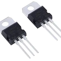
- Boost: A transistor (2N3055/TIP35/MOSFET) connected in parallel supplies additional current.
- Output: Stable 5V up to 10A reaches the load.
- Safety: Use heatsink, fan cooling, and proper wiring.
Testing & Final Adjustments
Check all the wiring after construction and stabilize the input voltage. Connect the circuit and apply a small load to it (e.g, 1A) and measure the output using a multimeter. Slowly add the load until the output voltage and temperature stabilize at 10A. Make sure that it does not drop under load with a voltage of less than 5V. In case of overheating, add larger heatsinks or cooling fans. Check the sharing and stability of regulators. Test resistive and inductive loads, such as a motor or an LED. Lastly, verify ripple, noise, or overheating. Alter the size of your heatsink, add filter capacitors (where required), and ensure a long-term full-load operation.
Frequently Asked Questions - 5v Regulator 7805 Upgrade to 10a:
Can a 7805 regulator supply 10A?
No, by itself it cannot. You need external pass transistors or a buck converter.
Which transistor is used with 7805 for 10A output?
Common choices include 2N3055, TIP35, or power MOSFETs like IRF540N.
What is the efficiency of 7805 with transistor booster?
It is low, around 40–60%, due to heat loss.
How much heat is generated at 10A load?
Dropping 12V to 5V at 10A causes about 70W heat loss.
Is switching regulator better than 7805?
Yes, buck converters are more efficient and suitable for 10A.
Do I need heatsink for 7805 10A circuit?
Yes, both 7805 and external transistors require large heatsinks and cooling fans.
Can I connect multiple 7805 in parallel?
Not recommended, as current sharing is uneven and unreliable.
What input voltage is required for 7805?
At least 7V DC, typically 9V–12V, depending on load.
Can I use 7805 for powering Arduino at 10A?
Yes, but only with booster circuit; otherwise it will overheat.
What is the best alternative to 7805 10A?
DC-DC buck converter modules rated for 10A output are the best choice.