How to Make a Simple Current Booster Circuit
Learn how to make a simple current booster circuit to drive high-current loads safely. Step-by-step DIY guide, components, schematic, and working principle.

What is a Current Booster Circuit?
An electric current amplifier is referred to as a current booster circuit. Although the voltage does not change much, the circuit enables a small input current to regulate a significantly large output current. The primary role here is to ensure that low-current controllers are not damaged when they are switching high-current loads.
Key points:
- Input is low-current (control signal).
- Output is high-current for the load.
- Voltage is usually similar to the input supply.
simple transistor current amplifier
A basic current booster circuit is a very fundamental DIY electronics project in the process of any individual wishing to drive bigger current loads with the use of a small current control signal. It enables one to use a small input current to regulate a bigger current to high-current devices such as motors, relays, lamps, or LEDs.
It is a project that hobbyists, students, and electronic enthusiasts would find useful as it provides them with a stable means of amplifying current without the need to redesign the power supply. The main amplification device of the circuit is typically a transistor or MOSFET. A microcontroller, switch, or sensor could be the input signal, and this takes charge of activating the transistor to produce increasingly more current to the load.
This guide gives a description of the principle of operation, parts usedstep-by-stepep instructions to construct, as well as a circuit diagram to build a simple, efficient, and safe current booster. With these instructions, you will easily be able to run devices with large currents without breaking your control circuit.
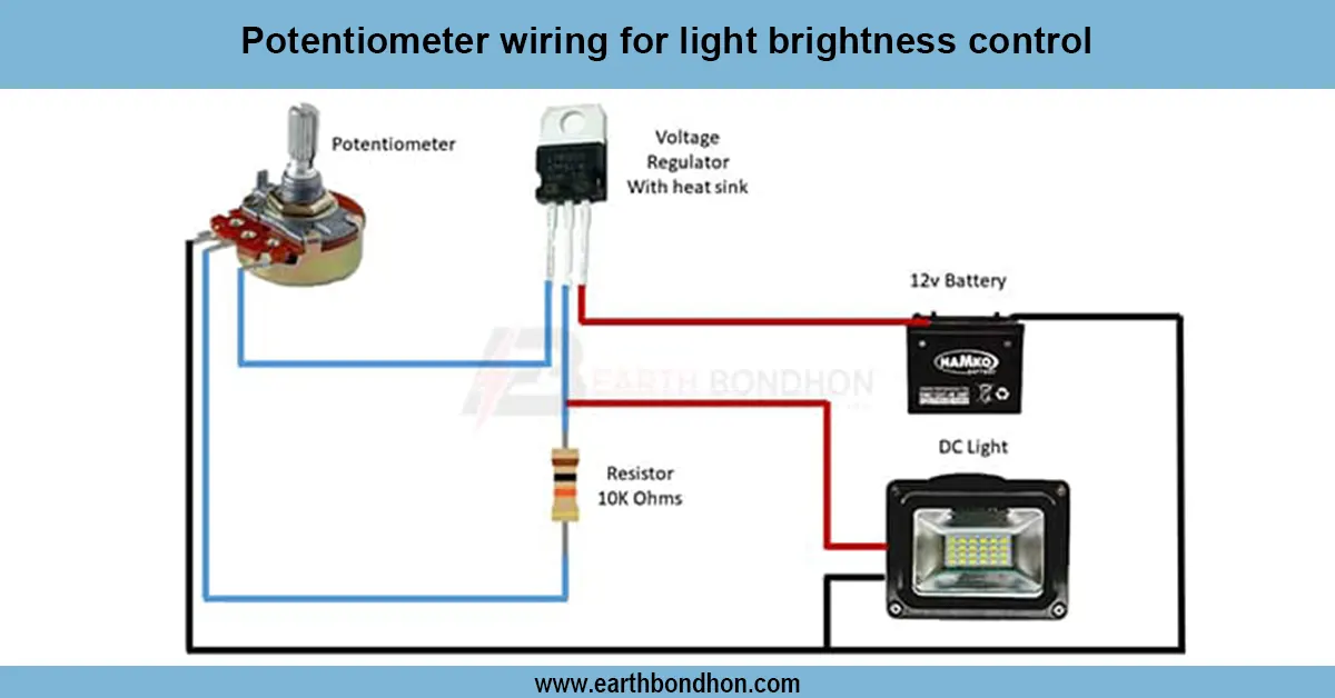
Applications of Current Booster Circuit
- Driving high-power LEDs or lamp arrays
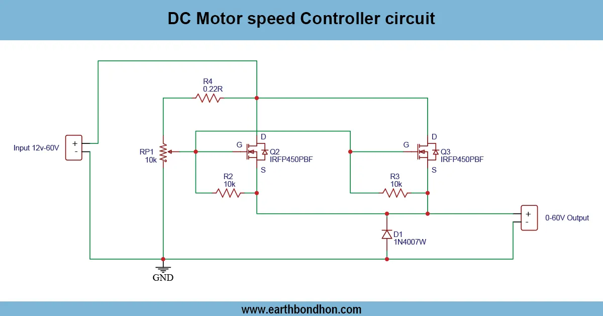
- Powering small motors or fans from a microcontroller
- Operating relays with low-current control
- Battery-operated projects needing high current
- Amplifying signal for DIY electronics projects
Components Required
| Component | Specification |
|---|---|
| Transistor | TIP31, TIP41, or MOSFET like IRF540 |
| Resistor | 1kΩ, 10Ω (base or gate current control) |
| Power Supply | 5V–12V (depending on load) |
| Load | Motor, LED, relay, or other high-current device |
| Capacitor | Optional: 100μF for smoothing |
| Heat sink | Required for high current load |
| Wires & PCB | For connections and assembly |
Working Principle
Transistor as Current Amplifier
A transistor acts as a current amplifier. A small current at the base controls a larger current flowing from collector to emitter.
Input-Output Relationship
Input current × current gain (hFE) = Output current
This allows low-current control devices to safely operate high-current loads.
Protection Features
- Add resistor at base to limit input current
- Add fuse for overcurrent protection
- Use heatsink for power transistor to prevent overheating
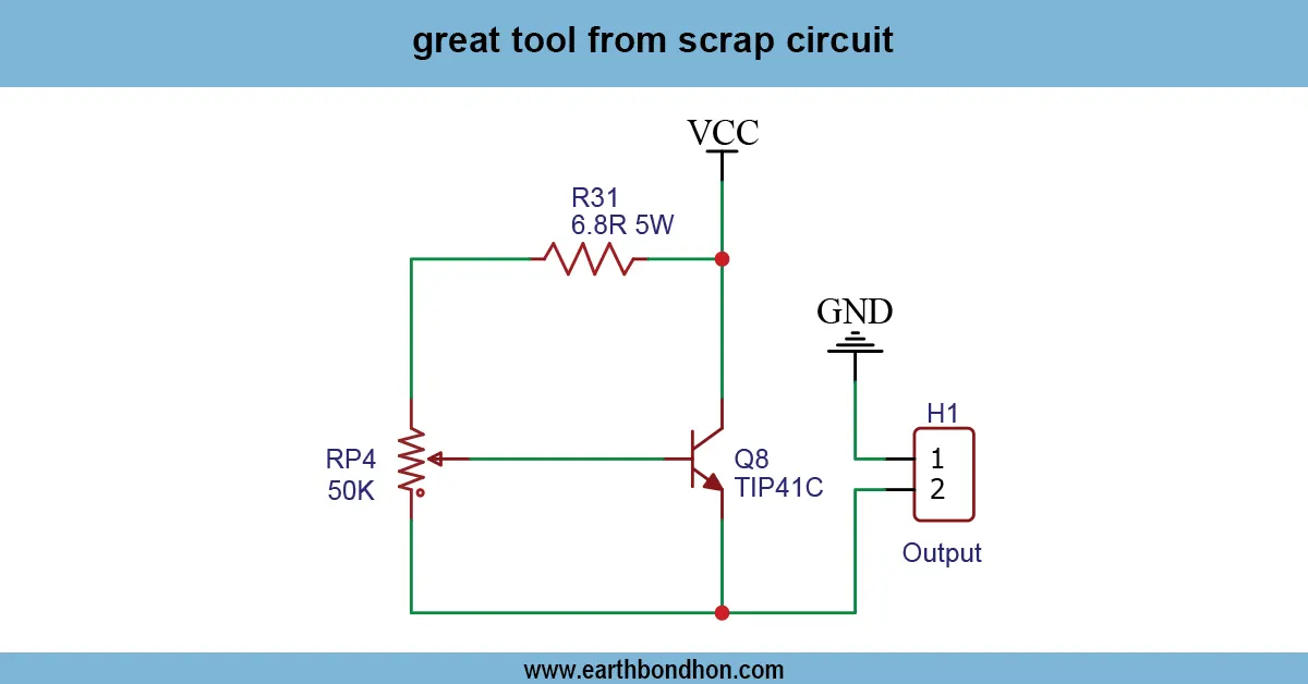
Circuit Diagram of Simple Current Booster
- Connect input control signal to transistor base via a resistor.
- Connect collector (or drain for MOSFET) to positive supply and load.
- Connect emitter (or source for MOSFET) to negative/ground.
- Add capacitor parallel to load for stability if required.
- Use proper heatsink for transistor.
- Fuse in series with load for safety.
Step-by-Step Construction Guide
- Place transistor on PCB or breadboard.
- Connect input control pin to transistor base/gate through resistor.
- Connect load to collector/drain.
- Connect power supply positive to load and emitter/source to ground.
- Add heatsink for power transistor.
- Test input signal at low current first.
- Gradually increase load while monitoring transistor temperature.
Tips for Maximum Efficiency
- Choose transistor with high current rating
- Use MOSFETs for low voltage drop and higher efficiency
- Keep wiring short to reduce losses
- Add smoothing capacitor to stabilize load current
Safety Precautions
- Do not exceed transistor current rating
- Ensure proper insulation of wires
- Use a fuse for overload protection
- Avoid touching transistor while powered
Troubleshooting Common Issues
Load Not Working
- Check transistor orientation
- Verify input control signal
Overheating of Transistor
- Use larger heatsink
- Reduce load current below transistor rating
Voltage Drop
- Ensure thick wires for load
- Check solder joints
Frequently Asked Questions - How to Make a Simple Current Booster Circuit:
What is a current booster circuit?
A circuit that amplifies a small input current to drive a high-current load.
Which transistor is best?
TIP31, TIP41, or IRF540 MOSFETs are ideal for boosting current.
Can it drive motors?
Yes, small DC motors or fans can be driven safely.
Do I need a heatsink?
Yes, for high-current loads, heatsinks prevent transistor overheating.
Can I use a microcontroller input?
Yes, the circuit can be triggered by low-current microcontroller pins.
What is the maximum current it can handle?
Depends on transistor rating, usually 3A–10A for TIP series.
Do I need a fuse?
Yes, to protect both the load and transistor.
Can I use a MOSFET instead of a transistor?
Yes, MOSFETs reduce voltage drop and increase efficiency.
Why is load voltage dropping?
Check wire thickness, solder joints, and transistor saturation.
Is this safe for beginners?
Yes, with low voltage and proper precautions, beginners can safely build it.