

Touch on-off Switch
7N80 touch on-off switch circuit toggles LEDs or relays with a fingertip, ideal for DIY electronics and home automation projects.

7N80 toggle switch:
The touch-on/off switch circuit of a 7N80 is an easy, contemporary substitute for a mechanical switch, in which devices can be switched on or off by simply touching the tip of a finger. With the 7N80 IC, it is possible to change the output states per touch, and this makes it suitable for LEDs, relays, and small appliances. Small and low power Consumption. It is ideal for DIY electronics, smart home applications, and educational use. It is a guide describing the operation of the circuit, input-to-output connections, and simple installation to enable novices and hobbyists to incorporate a company-tested, touch-controlled switching in their projects.
Electronic touch control:
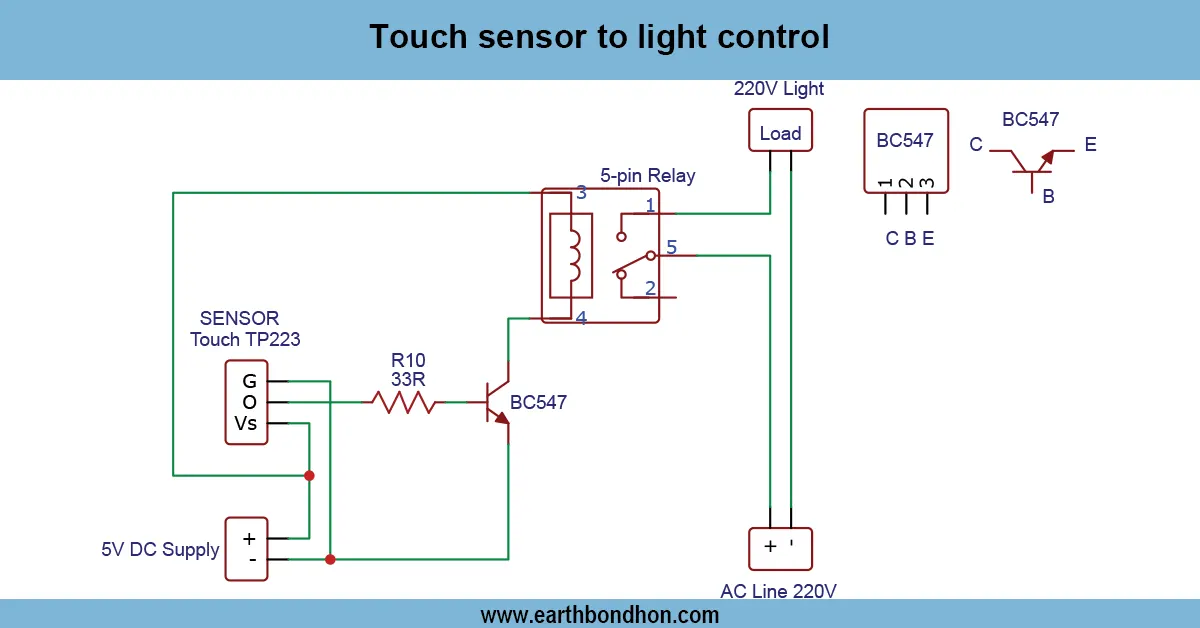
This is a simple and effective method of controlling LEDs, relays, or small appliances with only the tip of the finger, using a 7N80 touch-on/off switch circuit. It operates the 7N80 touch IC in a toggle mode whereby the state of the output is modified once the touchpad is touched, thereby removing the use of mechanical switches. The circuit is suitable for use in all DIY electronics projects, home automation, and education. Depending on the load and IC specification, it is driven using 3 -12V DC. The touchpad input is wired to the IC through a resistor, and the output wires to the LED or relay. Sensitivity is also adjustable by changing the values of the resistor or the capacitor to ensure a stable operation in a variety of environments. In case of higher power loads, a transistor/relay driver may be included. It is also easy to install on a breadboard or PCB, and with correct insulation, it can last a long time. A small, energy-saving touch switch offers an alternative, modern, mechanical-free means of switching devices in electronics projects, and offers a reliable and repeatable performance to hobbyists and beginners.
⚡ Work & Installation (Input → Output):
It operates on the 7N80 touch IC in the toggle mode. The IC changed its output state, and the connected LED or relay is turned on or off when the touchpad is pressed. The IC input is linked to the touchpad using a resistor, and the load is driven using the output pin. The placement of the IC, the resistors, capacitors, and touchpad is done on the breadboard or PCB. Depending on the IC requirements, power is supplied through a 312V DC source. The input will be the touch of the fingertip to the pad, and the output will be the activation of the LED or relay. In case of increased loads, a transistor may be inserted between the IC output and the device. It can be well insulated and has secure connections, such that its operation can be reliable and long-term, making it suitable for automating the home or for small-scale DIY electronics.
Testing & Final Adjustments:
Once the 7N80 touch-on/off switch is put together, power the circuit and touch the pad. It should be turned on and off with every touch. In case it does not react, test connections, especially the resistor between the touchpad and the IC input, and get the correct capacitor values. Tune sensitivity by changing the value of resistors or capacitors. The more the resistance, the less the sensitivity, ty and vice versa. Check that the IC is steady-voltage, and irregular switching can be the result of variable switching. To operate more powerful things, a transistor or relay driver circuit is needed. Ensure that the circuit does not get hot, and attach it to the PCB to make it long-lasting. Coat the strayed wires and make the touchpad available. When complete, the switch is reliable and can be used to switch devices every time a touch is made, and it offers a small, mechanical-free method of switching LEDs, miniaturized appliances, or home automation systems. Good testing results in long-term stability.
Frequently Asked Questions - Touch on-off Switch:
What is a 7N80 touch switch?
A switch that toggles output using the 7N80 IC on touch.
Which IC is used?
The 7N80 touch IC is used for toggle operation.
What power supply is required?
Typically 3–12V DC depending on load and IC.
Can it control high-power devices?
Yes, with a transistor or relay driver.
How sensitive is the touchpad?
Sensitivity can be adjusted with resistor/capacitor values.
Is it suitable for beginners?
Yes, ideal for DIY electronics and learning projects.
Can it drive LEDs directly?
Yes, LEDs or low-power relays can be connected directly.
Can it be mounted on PCB?
Yes, for stability and long-term use.
Does it need calibration?
Minor adjustments may be needed for touch sensitivity.
Is it energy-efficient?
Yes, consumes very low current when idle.