


Mini Project Motion Sensor
Detect motion easily with a simple BC547-based motion sensor circuit. Ideal for hobbyists and students for mini electronics projects and automatic alarms.

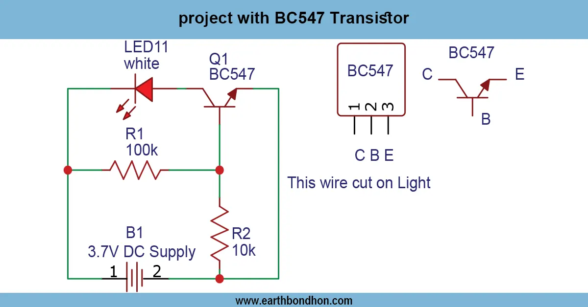
BC547 motion detector circuit
An example mini motion sensor project based on BC547 is a motion detecting motion sensor, which self-flips a load such as an LED or a buzzer, to provide a cost-effective motion detecting transistor-based motion detector project in DIY electronics projects.
PIR-less motion sensor DIY
The Mini Project: Motion Sensor Using BC547 is an easy electronics project based on detecting motion and turning on an LED or a buzzer. The BC547 transistor is used as a switch to activate/ deactivate the load when movement is detected. The circuit may use an infrared photodiode, LDR, or phototransistor instead of a PIR sensor to detect motion in the surrounding environment. The voltage across the base of the BC547 transistor varies when the light or infrared signal is changed by motion, causing the transistor to conduct and switch ON the LED or alarm. The project will be ideal for an intervention on students, hobbyists, and DIYers interested in learning about motion detection, transistor switching, and sensor-based automation. It is small, cheap, and can be built on a breadboard or on a small PCB. Other applications are small alarm systems, automatic lighting, and educational electronics applications.
Work / Installation (Inputs → Outputs)
- Power Input → 5–12V DC supply.
- Motion Detection Sensor → LDR, infrared diode, or phototransistor detects movement.
- BC547 Transistor → Switches the LED/buzzer ON/OFF based on sensor signal.
- Load Output → LED, buzzer, or small lamp activates when motion is detected.
- Installation → Assemble sensor, BC547, resistor, and load on breadboard or PCB; connect DC supply; adjust resistor/sensor sensitivity; verify transistor orientation.
Testing & Final Adjustments
When it has been assembled, power the circuit and then take your hand or an object close to the sensor. When motion is sensed, the LED or buzzer must come on, and when motion ceases, the LED or buzzer must go off. Adjustment of the series resistor to the correct transistor base current and the sensitivity of detection. Trial and error to make sure that the test is stable and reliable. Small alarms, automatic lighting, or learning electronics experiments should have the motion sensor properly tested to ensure that it operates consistently.
Frequently Asked Questions - Mini Project Motion Sensor:
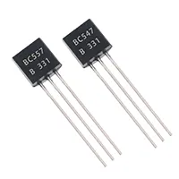
What is BC547?
It is an NPN transistor used for switching and amplification.
Can it detect motion?
Yes, using a photodiode, LDR, or phototransistor as a sensor.
What voltage is required?
Typically 5–12V DC supply.
Is it beginner-friendly?
Yes, simple components and easy assembly.
Can it drive a buzzer?
Yes, within the current rating of BC547.
How to adjust sensitivity?
Change the series resistor or position of the sensor.
Applications?
Automatic lights, mini alarms, and hobby electronics projects.
Do I need a PCB?
Optional; breadboard is sufficient for testing.
Can multiple sensors be used?
Yes, in parallel with proper base resistor.
Is it cost-effective?
Yes, uses inexpensive and widely available components.