


Sound Sensitive 12v Bulb Control
Automatic 12V bulb controller that turns lights ON with loud sounds (claps, voice). Uses a microphone/amp, comparator/transistor, and relay/MOSFET for safe 12V switching.

DIY sound-activated lamp 12V:
A sound-sensitive 12V bulb control is a device that has a microphone and a sound amplifier to detect loud noises and switch a 12V lamp ON or OFF. It converts audio into a clean switching pulse and switches the lamp on and off using a relay or MOSFET to give a reliable hands-free light.
clap activated 12V bulb circuit:
Sound Sensitive 12V Bulb Control circuit is an automatic bulb/lamp control that uses audio pulses (claps, shouts, or beats) to turn on or off a 12V bulb/lamp. The design involves a small electret microphone whose sound is converted into a voltage pulse that can be used with the help of a preamplifier (transistor or op-amp). A pulse shaping/comparator stage (as LM358 or a comparator) and a latching/monostable stage (with a flip-flop, 555 monostable, or transistor latch) are required to clean up that pulse into a clean ON/OFF command. The command circuit leads to a switching device, a relay to isolate, or an N-channel MOSFET/PNP/NPN stage to provide 12V lamp silent switching. Sensitivity and time-out/debounce are set with potentiometers and RC timing in case the light has a rattling bulb. The circuit is 12V and will suit hobbyists who require a simple automatic lamp, party light, hands-free lamp light control with safe battery operation, or safe DC-adapter operation.
⚡ Work & Installation (Input → Output):
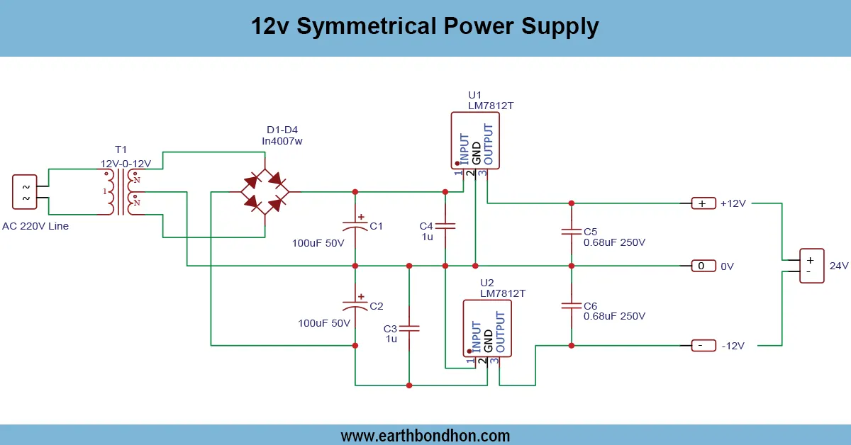
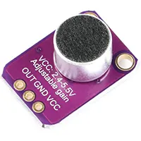
- Input (Audio & Power): Audio: Electret microphone picks up sound (clap/voice). Power: 12V DC supply for lamp and switching stage; 5–12V regulated supply for logic/amplifier if needed.
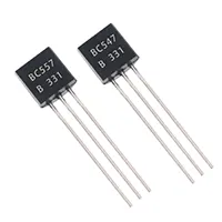
- Preamplifier: Microphone → coupling capacitor → small preamp (transistor or op-amp) to raise the tiny audio to logic level.
- Signal Conditioning: Rectifier/peak detector + RC filter to convert AC audio bursts into DC pulses. Comparator or threshold stage (LM358/LM393) turns pulses into digital HIGH/LOW.
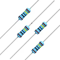
- Debounce / Latch: Monostable (555) or flip-flop latches the state (toggle or timed ON). Potentiometer adjusts sensitivity/time.
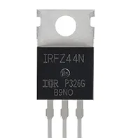
- Switching Stage: Comparator output drives a driver transistor or MOSFET (e.g., IRLZ44/logic MOSFET) or a small relay via a transistor driver for isolation. Switch handles the 12V bulb current; use appropriate device rating.
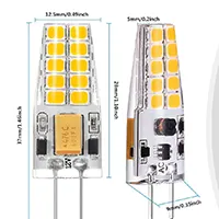
- Output (Bulb): Bulb positive → 12V supply; bulb negative → MOSFET/relay contact → supply negative (ground). Add flyback/snubber and reverse diode for inductive loads (relay coil).
- Installation: Mount microphone in unobstructed position; place circuit in enclosure; keep mains isolated (use only DC 12V for lamp). Test sensitivity and timing before final mounting.
Testing & Final Adjustments:
Begin testing using a current-limited 12 V supply or a small power LED lamp. Turn on the amplifier/logic first and make sure that the microphone preamp is sending out pulses when you clap - see on an oscilloscope or LED test point. Adjust the input potentiometer to adjust sensitivity to ensure that normal background noise does not operate it. Adjust the comparator threshold and the debounce/monostable timing: adjust the RC values until a single clap results in one clean ON/OFF cycle (or a timed ON in case the monostable is used). Ensure driver stage loads only when ordered, measure MOSFET temperature under load, and add a heatsink where needed. Arcing wiring check relay, Wiring to add a snubber (RC) across inductive loads. Lastly, run the system for a few minutes to check for no false triggers; adjust sensitivity and time constants for reliable operation. Never leave the control circuitry unchecked, and always ensure that it is not operating on any mains voltage; keep it well down in low-voltage current.