CD4017 Decade Counter IC Level Control Button
Build a CD4017 decade counter IC-level control with a button using simple components. Step-by-step guide includes circuit diagram, working principle, assembly, and troubleshooting for beginners.

Introduction to CD4017 Decade Counter Circuits
The CD4017 IC is a CMOS decade counter /divider IC that offers 10 decoded outputs with one input pulse. It is set up in this project to trigger sequential outputs when a button is pressed. IC may directly drive LEDs or may just use transistor drivers to control other loads. The project is also suitable to learn sequential logic, button debounce, and output level control in electronics.
simple diy electronics projects
The CD4017 decade counter IC level control with button is a simple and interactive electronic project that will enable you to get sequential outputs on the press of a button. The level indicator or sequence controller can be made in a step-wise fashion with the help of a CD4017 IC, a push button, and a couple of LEDs or other output devices. The button, with every press, takes the output to the next step and thus can be used with LED bar indicators, sequential lighting, or educational projects. The circuit is used to show how IC counters, debounce circuits, and sequential logic control work. Here we will discuss the ingredients, the working principle, circuit diagram, assembly, and troubleshooting information, so that the novices could construct a reliable and attractive level control circuit using the CD4017IC ..
Features of the Level Control Circuit
Simple Button Control
Each button press advances the output by one step. Eliminates mechanical switches for sequential activation.
Sequential Output Activation
LEDs or loads turn on one by one in sequence, providing a visual representation of output stages.
Adjustable LED Levels
The number of active LEDs can represent levels (1–10). Useful as a bar-graph display or level meter.
Components Required
- CD4017 Decade Counter IC: Provides 10 sequential outputs for each clock pulse.
- Push Button Switch: Acts as the clock input to advance the counter.
- LEDs or Output Loads: Visual indicators for each output. Small motors/relays can be used with transistor drivers.
- Resistors: Limit LED current; can be part of debouncing network.
- Capacitors: Used for debouncing the button to prevent multiple counts.
- Power Supply: 3V–15V DC depending on IC and output load.
Working Principle
IC as Decade Counter
The CD4017 counts pulses applied at its clock input. Outputs Q0–Q9 go HIGH sequentially with each pulse.
Button as Trigger Input
The push button provides a single pulse to the IC clock input. Capacitor-resistor network ensures proper debouncing.
Output Sequencing Mechanism
Each pulse activates the next output pin. Previous outputs may remain ON or reset depending on circuit design.
Circuit Diagram and Assembly Steps
Connecting the CD4017 IC Pins
- Pin 16: VCC
- Pin 8: GND
- Pin 14: Clock input connected to push button
- Pins 3, 2, 4, 7, 10, 1, 5, 6, 9, 11: Outputs Q0–Q9
Wiring Button and Debounce Circuit
Connect the push button to the clock input with a resistor and a capacitor in a debouncing configuration to prevent multiple pulses.
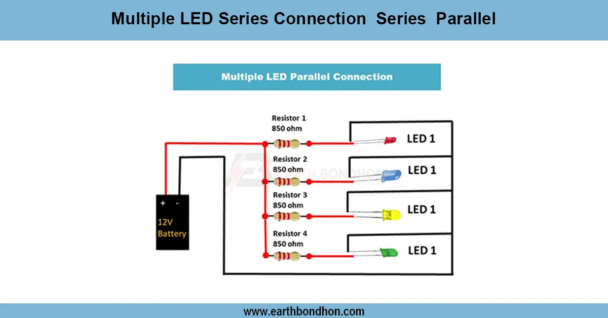
Connecting LEDs or Loads
Each output pin connects to an LED via a resistor. For high-power loads, use a transistor-based driver.
Testing and Adjusting Level Control
Power the circuit and press the button. Outputs should advance sequentially. Adjust the debounce capacitor for accurate counting.
Applications of CD4017 Level Control Circuit
- LED bar-graph level indicators
- Step-wise lighting sequences
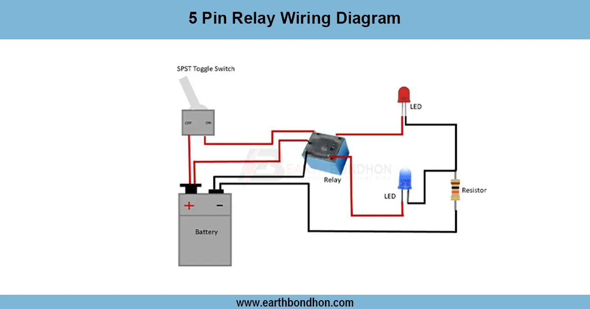
- Sequential relay control
- Beginner electronics learning projects
- DIY level meters or counters
Safety Precautions
- Use current-limiting resistors for LEDs.
- Observe correct IC polarity.
- Use transistor/relay isolation for high loads.
- Test with low-voltage DC before attaching AC devices.
- Avoid touching live circuits.
Troubleshooting and Maintenance
- Outputs not advancing: Check clock input and debounce components.
- Multiple outputs toggle: Increase debounce capacitor value.
- LED not lighting: Check resistor and LED orientation.
- IC heating: Verify power supply level and wiring.
- Loose connections: Ensure proper wiring or soldering.