
Without IC Chaser LED Relay Based Project
Build a relay-based LED chaser project without using ICs. LEDs sequentially blink using relays, providing a simple DIY electronics display for beginners and hobbyists.

DIY LED sequence without IC:
An LED chaser circuit inon-IC-basedn-IC, simple electronics project, during which LEDs are winked in series through relays rather than ICs. The circuit is designed to produce a moving light effect, which is pleasing and informative to the ey,e and communicates via each relay in the circuit to an LED. In this project, the fundamental elements of electroni,cs such as the working of the relay, tim,ing and sequencing switc,hing have been shown. It is gfornovicesnovice and hobbyists who would like to know about relays, timers, and LED driving circuits. The, chaser using, a relay has spare parts that ensure longevity, and allows it to be customized to be used in decorative lighting, DIY displays, or electronics experimentation with minimal cost and proper wiring.
LED blinking project:
An LED chaser using IC-free relays is a simple and educational electronics project, in which LEDs flash sequentially using relays, not using integrated circuits. Each relay, in this circuit, is then linked to an LED and is switched on and off in a time-timed randomized sequence, producing a moving light effect that is aesthetically pleasing. Resistors and capacitors control timing and regulate the delay between the activation of every relay. Diodes are applied between relay coils to guard the circuit against back EMF. The project is recommended to beginners and hobbyists who wish to know more about the operation of relays, timing circuits, and sequential control of an LED. It is cheap, long-lasting, and can be extended with additional relays and LEDs to have long sequences or decorative light effects. The LED chaser based on relays can be used to construct reliable and smooth sequential operation of LEDs when it is properly assembled, wired and tested, and is thus suitable in DIY projects, educational l,abs and decorative electronics projects.
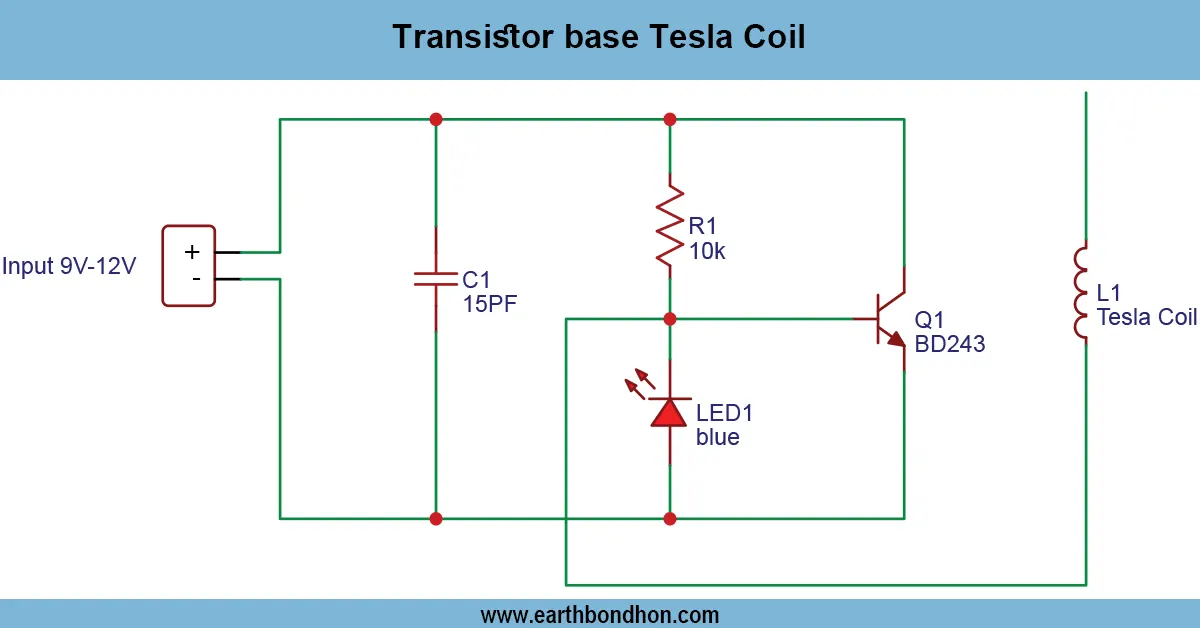
⚡ Work & Installation (Input → Output):
The operation of the relay-based LED chaser is that a number of relays are wired in a daisy chain of switching. All the relays are activated and deactivated in a synchronized order, and this makes all the LEDs connected to it blink sequentially. The resistors and the capacitors regulate the timing so that the relay is activated later, creating the chaser effect. Installation It is necessary to connect the LEDs to the relay contacts, to place relays in series and to run the relay coils on the control circuit fed by a DC source. Make sure that the polarity is correct and apply diodes on the relay coils to avoid damage to components by back EMF. This construction makes the use of ICs unnecessary but has a visible sequential LED display. The project is secure and also dependable, and can be extended by the inclusion of extra relays and LEDs to either prolong the sequence or to include decorative impacts.
Testing & Final Adjustments:
Once the relay-based LED chaser has been assembled, it has to be connected to an adequate DC power supply. Check the sequence of switching on the lighting one after another, making sure that the relays are working. Change the values ofthe resistor and the capacitor in the timing circuit when the LEDs are blinking either too fast or too slow. Ensure that the LEDs are properly mounted and the diodes are mounted on opposite sides of the coils in the relay to avoid damage caused by the spikes of the voltage. Check various loads or LED configurations to be sure that it operates in sequence. Make sure that relays are suitable for the supply voltage and LED current. Check the circuit in the first operatio for, overheating or improper activation. Increase or decrease timing elements to get the plot of LED sequences. After being tested, the LED chaser using a relay offers a stable and aesthetic repetitive light effect which does not need ICs. It is a good project to start with, for hobbyists and DIY electronics lovers who desire an inexpensive, educationa,l and appealing LED display.