Creators
Md Jony Islam Author
Md Jony Islam
CalculatorToolsProjectExpert
Reviewers
Małgorzata Koperska, MD Steven Wooding
Last updated: January 14, 2026

12V Symmetrical Power Supply Circuit | Dual Voltage Power Design

🇺🇸
English
Default
🇪🇸
Español
Spanish
🇫🇷
Français
French
🇩🇪
Deutsch
German
220V AC to 2×12V Transformer

220V AC to 2×12V Transformer

Step-down transformer that converts 220V AC mains to two 12V AC outputs

1N4007 Diode

1N4007 Diode

General-purpose 1000V, 1A diode

1000µF Capacitor

1000µF Capacitor

Large electrolytic capacitor with 1000 microfarads

LM7812 Voltage Regulator

LM7812 Voltage Regulator

Fixed positive voltage regulator (commonly 5V, 12V, 15V)

*Please note: These are affiliate links. I may make a commission if you buy the components through these links. I would appreciate your support in this way!

Transformerless 12v Power Supply

Build a 12V symmetrical power supply circuit to provide +12V, -12V, and ground output for audio amplifiers, op-amps, and other dual-voltage electronics projects...

battery series switch wiring:

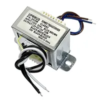
In order to construct a 12V symmetrical power supply, one has to tie the AC mains to a step-down center-tapped transformer, followed by a bridge rectifier to convert the AC into DC. Connect the center tap as ground, filter the output with capacitors, and control with 7812 (+12V) and 7912 (-12V) ICs. This includes +12V, -12V, and ground output where there are two-voltage circuits.

variable voltage and current power supply

A Strong voltage and current controllable power supply circuit is a flexible electronic project that enables the user to regulate the output voltage and current to supply various electronic circuits without risking their safety. This kind of power supply is needed during testing, prototyping, and electronics experiments where voltage and current are needed with high precision.

The adjustable power supply circuit operates on the principle of controlling the voltage with a series pass transistor or regulator IC, and a current restrictive circuit prevents the erroneous state of the load. The users will be able to adjust the potentiometers by setting the desired value of the output voltage and current. This form of DIY project serves not only to offer a useful power supply in a laboratory, but also to allow learners to appreciate the concepts of voltage regulation, current limiting, and feedback use in electronics. Here we will discuss the parts, working principle, circuit diagram, step-by-step construction, and troubleshooting of the construction of a powerful voltage and current adjustable power supply circuit.

DIY Adjustable Power Supply Circuit Guide

Advantages of Using an Adjustable Power Supply

  • Versatility: Supports a wide range of voltages and currents.
  • Safety: Protects sensitive circuits with adjustable current limiting.
  • Precision: Fine-tune output voltage and current for experiments.
  • DIY Learning Project: Understand regulation and feedback control.
  • Reusable: Suitable for multiple projects without buying new adapters.

Components Required for DIY Circuit

Component Quantity Purpose
LM317 Adjustable Regulator IC1Controls output voltage
NPN Power Transistor (TIP3055)1Handles high current
Resistors (0.1Ω – 1kΩ)MultipleVoltage divider & current sensing
Potentiometers (5kΩ – 10kΩ)2Adjust voltage & current
Capacitors (10µF – 100µF)2–3Filtering & stability
Diode Bridge / Rectifier1Converts AC to DC
Heatsink1Dissipates heat
LED1Power indicator
Fuse1Protection
Transformer1Steps down AC voltage
Breadboard / PCB1Circuit assembly
Jumper WiresAs neededConnections

Working Principle of the Circuit

Voltage Regulation Stage

LM317 regulates output voltage using a potentiometer for fine adjustment.

Current Limiting Stage

A sense resistor checks current flow. If it exceeds the set limit, the transistor limits the output.

Protection Features

  • Fuse prevents short-circuit damage.
  • Heatsink prevents overheating of LM317 and power transistor.

Power Supply Stage

Transformer AC → Bridge Rectifier → Filter Capacitor → Smooth DC → LM317 adjustable regulator output.

Circuit Diagram Explanation

  • Transformer Output → Bridge Rectifier → Filter Capacitor
  • LM317 sets output voltage via potentiometer
  • Current Sense Resistor monitors current
  • NPN Power Transistor supplies high current
  • Potentiometer sets maximum output current
  • Fuse & LED for protection and power indication

Step-by-Step Construction Guide

Step 1 – Power Supply Stage: Connect transformer to bridge rectifier, then add filter capacitor.

Step 2 – Voltage Regulation Stage: Connect LM317 to DC supply and adjust voltage potentiometer.

Step 3 – Current Limiting Stage: Insert sense resistor and connect transistor for current control.

Step 4 – Load Connection: Connect load through fuse for protection.

Step 5 – Testing & Calibration: Adjust voltage and current using potentiometers; verify with multimeter.

Applications of Adjustable Power Supply Circuits

  • Testing microcontroller circuits & sensors
  • LEDs, motors, battery charging projects
  • Electronics labs and DIY workbench
  • Prototyping and troubleshooting
  • Educational electronics training

Troubleshooting Tips

  • Output voltage unstable: Check LM317 input capacitor and heatsink.
  • Current limit not working: Verify sense resistor and transistor wiring.
  • Overheating: Improve heatsink or reduce load current.
  • Fuse blowing: Check for shorts or overloaded output.
  • Output voltage too low: Recheck transformer and adjust potentiometer.

Frequently Asked Questions - Transformerless 12v Power Supply:

What is a 12V symmetrical power supply?

It is a dual power supply that provides +12V, -12V, and ground.

Why is it used in op-amps?

It allows op-amps to swing output both positive and negative around 0V.

What transformer is used?

A center-tapped transformer is used to provide dual AC outputs.

Which rectifier is needed?

A full-wave bridge rectifier is used for symmetrical supply.

Which IC regulators are used?

7812 for +12V and 7912 for -12V regulation.

What is the ground point?

The transformer’s center tap acts as the ground.

What capacitors are needed?

Large electrolytic capacitors for filtering and small ceramic ones for stability.

Can I use it for audio amplifiers?

Yes, it provides dual supply essential for low distortion audio circuits.

How to test the supply?

Use a multimeter to check +12V and -12V relative to ground.

What happens if ground is not connected?

The circuit will not get correct symmetrical voltages, causing malfunction.

Comments

Please login to comment.

Md Jony Islam

Md Jony Islam

Calculator Tools Project

Founder of Earthbondhon.com

a free online tools website designed to make everyday and engineering-related calculations easier for students, professionals, and hobbyists. The site offers a wide range of basic calculators across key categories, including Electrical Calculators, Electronic Calculators, and Time & Date Calculators.