


Delay LED Light Circuit
Control the LED light with an adjustable delay using a BC547 transistor. Simple RC-based timing circuit for smooth LED ON/OFF transitions in DIY projects.

adjustable LED on-off delay
BM547 is a Delay LED light circuit that offers smooth LED turn-on/off timing. The transistor switches slowly using an RC network, with the delay being adjustable to lighting applications.
DIY LED delay controller
The Delay LED Light Circuit with BC547 enables the controlled turn on/off of an LED with a delay, which lets the transitions be smooth. An example of an NPN transistor used extensively is BC547, which is a switch driven by an RC (Resistor-Capacitor) timing network. As the input is converted, the capacitor charges or discharges through the resistor, which progressively switches the transistor on or off. The LED is lit up based on the conduction of the transistor, giving a variable delay based on the values of the RC. It is ideal for lighting staircases, indicator lamps, hobby electronics, and ornament lighting. The delay time may be adjusted by adjusting the resistor or capacitor. It is a simple design that is cheap and simple to assemble on a PCB or a breadboard. It is also appropriate for novices who need to know about timing circuits and switching with a transistor.
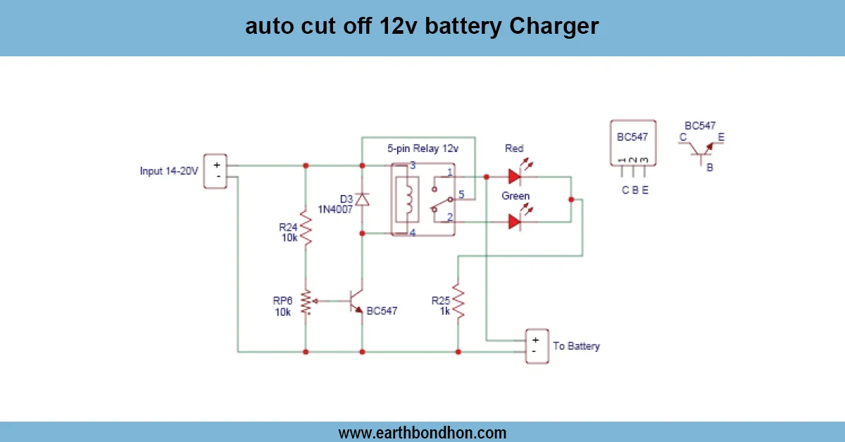
Work / Installation (Inputs → Outputs)
- Power Input → DC supply (e.g., 5–12V).
- RC Network → Resistor and capacitor create charging/discharging delay.
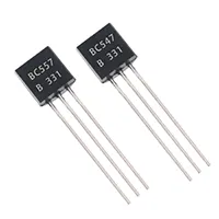
- BC547 Transistor → Acts as a switch to control LED.
- Output → LED turns on/off gradually according to RC timing.
- Installation → Assemble on PCB or breadboard; connect LED and resistor properly; adjust RC values to set desired delay.
Testing & Final Adjustments
Once assembled, connect the power supply and note the operation of the LEDs. The delay can be varied by changing the values of resistors or capacitors. Make sure that the LED does not flicker. Check to ensure that the BC547 transistor is not overheating when using it. Test at different levels of voltages to ascertain a stable performance. Adjust RC values to best delay effect. This is because proper testing will provide a quality and efficient delay LED light that can be used as a staircase lighting, ornamentation, and hobby electronics project.