

USB Voltage Protector Circuit
Protect your USB devices with a simple IRFZ44N MOSFET-based voltage protector circuit that prevents overvoltage, short-circuits, and device damage effectively.

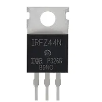
IRFZ44N MOSFET USB circuit:
The USB voltage protector is a device that protects your USB-powered devices against overvoltage, short-circuiting, and accidental damage with a USB voltage protector that uses the IRFZ44N MOSFET. The IRFZ44N is an electronic fuse that switches between electrical power on the USB when the voltage is more than a safe level. The miniature circuit is suited to DIY electronics, hobbyists, and makers, who often need access to USB charge and power banks or computer ports. The protector includes zener diodes, resistors, and the MOSFET that allows it to control the voltage and to respond immediately to save the devices that are connected. This is a guide on how to operate a reliable USB voltage protector circuit, its working principle, its wiring, and the safe operation of this circuit.
USB short-circuit protection:
A USB voltage protector circuit based on the IRFZ44N MOSFET protects the devices connected to the USB port against overvoltage and short-circuit, as well as inadvertent damage. The IRFZ44N is an electronic fuse intended to be used as a switching fuse, and the load can be switched on in nominal conditions and switched off instantly when the specific input voltage surpasses a safe value. To measure and turn on the MOSFET as required, the circuit would usually consist of a zener diode and resistors to measure the voltage and turn on the MOSFET. It is very small and affordable and can be used to secure smartphones, laptops, power banks, microcontrollers, and other USB-powered devices. When using MOSFETs, correct assembly is to connect the USB power line with the MOSFET drain, the device with the MOSFET source, and the resistor-zener network with the gate. The protector will be tested it activates in case of overvoltage conditions, an insulation, and safe PCB mounting should offer safety and reliability. This self-assembled USB voltage protector is an effective, reusable, and portable device that can be used to protect the equipment against damage, thus it can be utilized by hobbyists, electronic enthusiasts, and those who often use USB chargers or portable power sources.
⚡ Work & Installation (Input → Output):
The IRFZ44N USB voltage protector operates by regulating the current going through the MOSFET depending on the input voltage. In normal operation, the MOSFET will conduct the current, which will operate the USB device. The zener diode becomes activated when the input voltage rises above a safe value and this will switch off the MOSFET and break the load, in effect stopping overvoltage. Installation ion This can be done by connecting the MOSFET drain line to the USB power line, the source line to the device, and the gate line through the zener diode and resistor network. The circuit is powered directly off the USB 5V supply and does not require the use of an external power source. Safety and portability are guaranteed by proper insulation and compact PCB construction. The configuration avoids the damage of devices by accidental voltage spikes, short-circuits, or faulty USB chargers, which is why it is suitable for laptops, phones, microcontrollers, and other USB-powered devices.
Testing & Final Adjustments:
Once connected to the USB voltage protector and the regulated 5V supply, test the IRFZ44N USB voltage protector and use a device powered by a USB. Check the voltage at the output to make sure that it is functioning normally at normal conditions. To test protection, ensure that the input voltage is slightly higher than 5V and the MOSFET is cut of, then the device is protected. Ensure that the zener diode activateatin the right voltage. Check all connections and make sure to mount the MOSFET on a small heatsink in case of higher currents. Cover all open connections and wires with insulation to avoid a short circuit. Adjust resistor values as necessary to adjust voltage sensitivity. A USB adapter or a portable power bank casing can be fitted to the circuit to make it compact. Effective testing makes the protector responsive to the voltage spikes such that the USB devices are not damaged. It is very cheap, efficient, and reliable when safely assembled to protect your gadgets against overvoltage and short-circuits.
Frequently Asked Questions - USB Voltage Protector Circuit:
What is a USB voltage protector circuit?
A circuit that protects USB devices from overvoltage and short-circuits using components like MOSFETs and zener diodes.
Which MOSFET is used?
IRFZ44N, a fast-switching N-channel MOSFET.
How does it protect devices?
It disconnects the USB output when voltage exceeds safe limits or a short-circuit occurs.
Can it handle 5V USB devices?
Yes, it is designed for standard 5V USB-powered gadgets.
Do I need additional components?
Yes, resistors and zener diodes are used for voltage sensing and triggering.
Is it suitable for DIY projects?
Yes, compact and easy to build for hobbyists and makers.
Can it protect phones and laptops?
Yes, it safeguards any USB-powered device from overvoltage.
Does it require a heatsink?
Recommended if charging high-current devices to prevent MOSFET overheating.
Is it reusable after triggering?
Yes, it resets automatically when voltage returns to safe levels.
Can it be used with power banks?
Yes, it can be integrated into USB power banks or adapters for protection.