Remote Control On Off Switch Board Circuit
Build a remote control on/off switch board circuit at home. Step-by-step guide with components, working principle, schematic, and construction tips.

What Is a Remote Control On/Off Switch Board Circuit?
An electronic system to control wirelessly an AC or DC device is a remote control on / off switch board circuit. It comprises of a transmitter, a receiver and switching components like relays or MOSFETs.
home appliances remote control circuit
On/off switch board circuit incorporates a remote control in which the user can control electronic devices easily without touching the switch. This circuit is also very common in home automation, lighting systems, appliances, and amateur electronics.
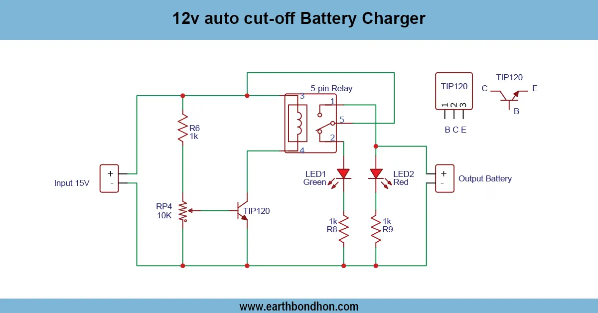
The circuit of the remote switch board is operating off the transmitter (RF/IR remote) and receiver module. The remote button is pressed and the receiver activates a relay or electronic switch to turn the device connected on or off. This project is suitable for acquiring knowledge on wireless control, relays, and switching of power. In the guide, we are going to describe the components, the working principle, the schematic diagram, the step-by-step method of construction, and also the troubleshooting tips to permanently construct a remote-controlled switchboard at home.
Remote Control Switch Board
High-level overview, components, working principle & applications
Frequently Asked Questions - Remote Control On Off Switch Board Circuit:
What is a remote control switch board circuit?
A circuit that allows switching electronic devices ON or OFF wirelessly.
Which modules are used?
RF or IR transmitter and receiver modules are commonly used.
How does the relay work?
The relay is activated by the receiver output via a transistor to switch the load.
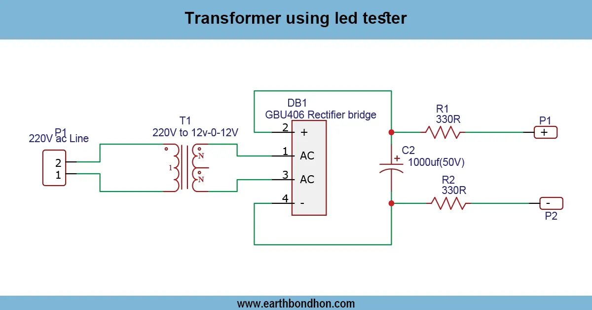
What voltage is needed?
Typically 5V–12V DC to power relay and receiver.
Can I control AC devices?
Yes, using a relay rated for AC voltage and current.
Is it safe for beginners?
Yes, for low-voltage DC control; take caution with AC loads.
Can I control multiple devices?
Yes, use multiple relays or multi-channel remote modules.
Do I need a flyback diode?
Yes, across relay coil to prevent transistor damage.
Can I use a smartphone remote?
Yes, with compatible IR or WiFi transmitter modules.
Is LED indicator necessary?
Not necessary, but it shows relay ON/OFF status for convenience.