

LDR Project
Build an LDR-based light sensor circuit using BC547. Detect ambient light levels to control LEDs or relays automatically for DIY electronics projects.

LDR BC547 light sensor circuit
One of the applications of the LDR project is flipping lights, such as LEDs or relay,s based on the amount of light present in the environment with the help of a BC547. It is perfect to study the idea of transistor switching and to creathomemadede light-sensitive circuits.
simple light detection project
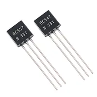
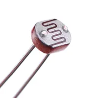
LDR Project Using BC547 is a simple electronic circuit to measure the amount of light present in the environment and use it to power a load automatically, in this case, an LED or a small relay. The LDR is a type of resistor that varies its resistive value with the intensity of light. BC547 is an NPN transistor that is used as a switch to switch the load ON or OFF depending on the voltage on the LDR. At a certain point of light level, the voltage on the LDR activates the BC547 transistor, and the device connected to it is operated. In bright light, on the contrary, the transistor becomes non-conducting, putting the load OFF. The students, hobbyists, and beginners who learn about the light sensors, transistor switching, and automatic control circuits would find this project to be ideal. Components are cheap and can be fitted on a PCB or breadboard. The series resistor is adjusted with the LDR, so that you can adjust the light sensitivity to what you want. They can be used as automatic night lamps, garden lights, or simple lights to trigger an alarm.
Work / Installation (Inputs → Outputs)
- Power Input → DC supply (5–12V).
- LDR Sensor → Senses ambient light levels.
- Voltage Divider → LDR and resistor set threshold voltage.
- BC547 Transistor → Switches load ON/OFF based on sensor voltage.
- Load Output → LED, relay, or small device controlled automatically.
- Installation → Assemble circuit on PCB/breadboard; connect LDR, load, and DC power; adjust resistor for desired light sensitivity.
Testing & Final Adjustments
Once assembled, supply DC and monitor the LED or load behavior under different light conditions. Darkness (cover the LDR): the BC547 is expected to conduct and to put the load ON. Let it be exposed to bright light, and the transistor must cease to conductt and the load should be turned off. The variable series resistor to adjust sensitivity. Check all connections to ensure that they are stable and well-oriented transistors. Several test cycles provide a good deal of switching reliability and consistency. Correct testing will guarantee that the LDR circuit has been successful in achieving automatic night lamps, garden lights, or alarm-activated lights.