Delay Led Circuit
Learn how to build a Delay LED Circuit, its working principle, wiring diagram, components, and step-by-step guide to delay LED turn ON/OFF.

What is a Delay LED Circuit?
The delay LED Circuit is intended to switch an LED ON or OFF after a set time. The delay is done by charging a capacitor with the help of a resistor (RC circuit) or by means of a timer IC. The application of this kind of circuit is found in cases where it is important to indicate sequentially or delayed manner
LED delay timer circuit
A delay LED Circuit is an electronic circuit in which an LED is activated or deactivated after a delay of a given time period. It finds extensive application in indicator lights, sequential lighting, and automation. The delay is manageable as a time constant of a resistor-capacitor (RC) or transistor circuit or timers in ICs such as the 555 timer.
This tutorial describes the principle of operation, parts, and wiring of a delay LED circuit and its construction step by step. You will also know how to change the delay time, troubleshoot problems that are related to it, and use the circuit in other projects. With this guide, amateurs and beginners can construct stable circuits to act as LED indicators, warning lights, and other decorative purposes.
Components Required for the Circuit
- LED (any color)
- Resistors (1kΩ – 1MΩ for timing)
- Capacitors (10µF – 1000µF for delay)
- Transistor (BC547, 2N2222) or IC 555 timer
- Diode (optional for polarity protection)
- DC Power Supply (5V–12V)
- Breadboard or PCB and connecting wires
Working Principle of Delay LED Circuit
RC Time Constant
The resistor and capacitor form an RC network. The time taken to charge or discharge the capacitor determines the delay time: \( t = R \times C \)
Transistor or IC Switching
When the capacitor charges to a threshold voltage, the transistor conducts and turns the LED ON. Using a 555 timer in monostable mode can also produce a precise delay time for the LED.
LED Turn ON/OFF Delay
- Initial power: capacitor starts charging.
- After delay: transistor switches, LED lights up.
- Turning off: capacitor discharges, LED turns OFF gradually if circuit is designed for off-delay.
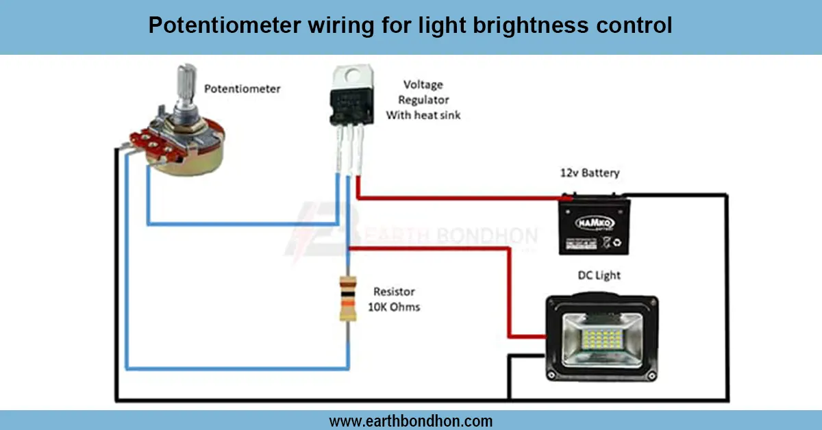
Delay LED Circuit Wiring Diagram
- Connect the resistor in series with the capacitor to form an RC network.
- Connect the transistor base to the capacitor via the resistor.
- Connect the LED anode to the collector of the transistor and the cathode to the ground.
- Apply a DC supply to the circuit.
- LED will turn ON after the capacitor charges to the threshold voltage.
- For IC-based delay, connect a 555 timer in monostable configuration with a resistor and a capacitor to set the delay time.
Step-by-Step Construction Guide
- Place the transistor or IC on the breadboard.
- Connect the RC network to the base pin of the transistor or the trigger pin of the 555 IC.
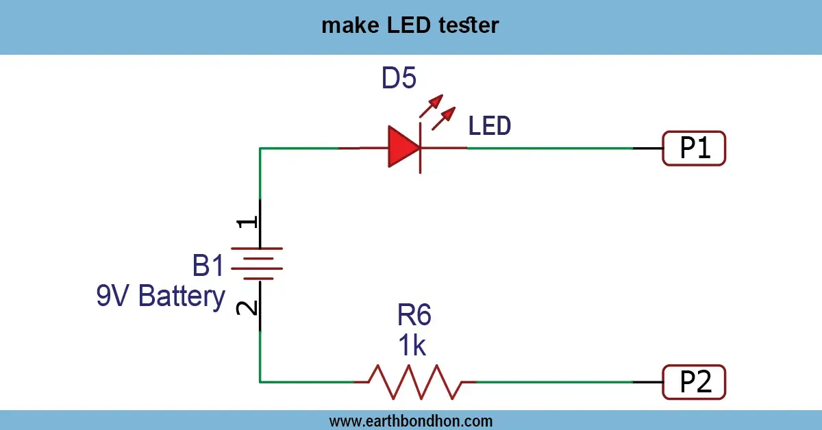
- Connect the LED with a current-limiting resistor.
- Connect the DC power supply to the circuit.
- Adjust the resistor and the capacitor to achieve the desired delay time.
- Power ON the circuit and observe the LED turning ON after a delay.
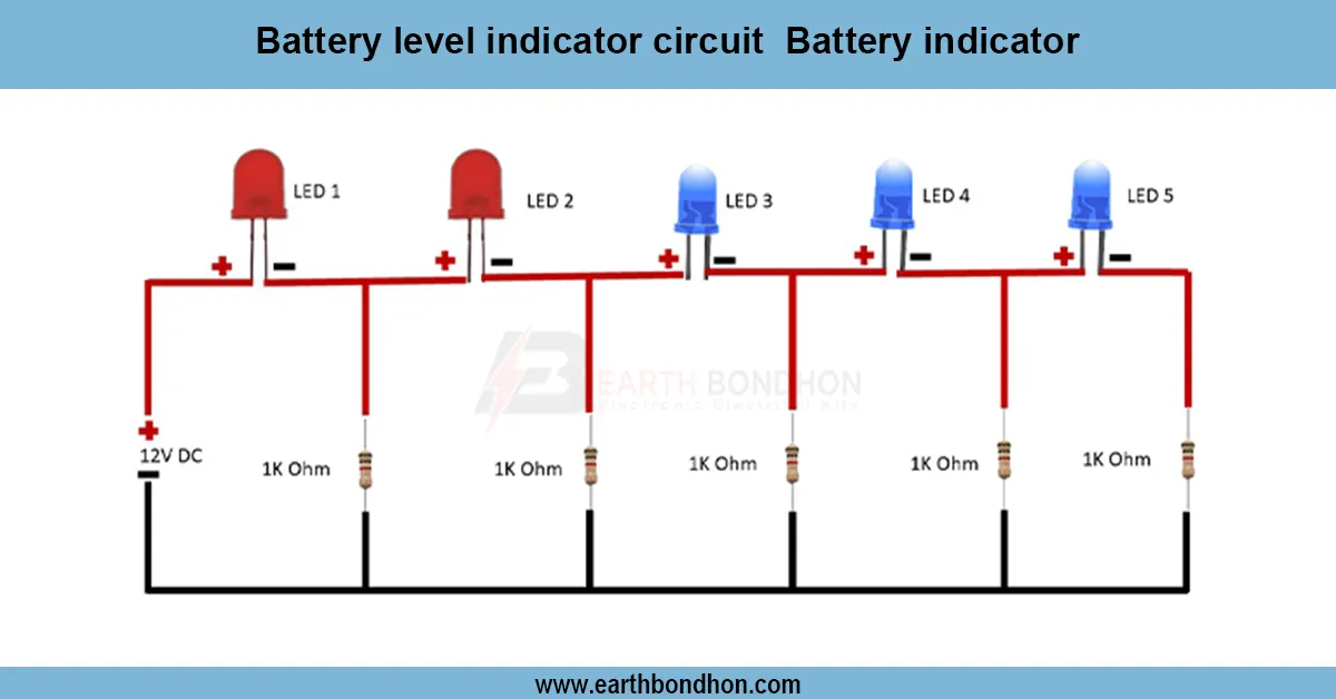
- For multiple LEDs, replicate the RC network or cascade 555 timers.
Applications of Delay LED Circuit
- Sequential lighting projects
- Warning indicators with delayed activation
- Power-on LED indicators
- Decorative light patterns
- Electronics hobby and learning projects
- Automotive LED delay indicators
Troubleshooting Common Issues
LED Does Not Turn ON
- Check LED polarity and transistor wiring.
- Verify capacitor charging and resistor connections.
LED Turns ON Immediately
- Increase the capacitor value or the resistor to increase the RC time constant.
- Check for short circuits across the capacitor.
LED Flickers
- Ensure stable DC supply.
- Use a capacitor with low ESR for stability.