Opticoupler Driver Circuit for 2 Output Transformers Circuit
Learn to build an optocoupler driver circuit for 2 output transformers. Step-by-step DIY guide with components, working principle, schematic, and troubleshooting.

What Is an Optocoupler Driver Circuit?
An optocoupler driver circuit is an electronic interface that involves optocouplers to separate the input control signal, which is applied, and the high-power output stages. The optocoupler is a single package that is a combination of a phototransistor and an LED. With the LED energized, the LED produces light to energize the phototransistor, which can then be used to produce other driving circuits, like windings in a transformer primary.
pc817 optocoupler driver circuit for two transformers
The circuit of an optocoupler driver that drives 2 output transformers is a dependable technique of regulating various outputs of the transformers with a single signal input, and still maintains electrical isolation. With optocouplers, a high voltage circuit on the transformer side may not damage or cause signal loss to the control side (low voltage side).
The circuit of the optocoupler driver of 2 output transformers operates to change an electrical signal as an input to an optical signal using the LED of the optocoupler. This optical signal causes one of the transistors within the optocoupler to be activated, which in turn drives other external transistors or MOSFETs attached to the primary side of the transformers. All transformers may or may not be synchronized to be independently driven, depending on the design. The device finds application in many inverter applications, two-output power supply, isolation amplifier, and automation in industry applications, where it is vital to isolate the transformer and control the power at very fine settings. This tutorial describes the parts, circuit, and construction of a working circuit step-by-step assembly, as well as troubleshooting hints to construct a strong dual transformer optocoupler driver.
Advantages of Using Optocouplers for Transformers
- Electrical Isolation: Protects low-voltage control circuitry.
- Noise Immunity: Reduces interference from high-voltage circuits.
- Safety: Minimizes risk of electric shock.
- Precise Switching: Accurate control of transformer primary signals.
- Dual Output Support: Can drive multiple transformers independently.
Components Required for DIY Circuit
| Component | Quantity | Purpose |
|---|---|---|
| Optocoupler (e.g., 4N25, PC817) | 2 | Isolated input control |
| NPN/PNP Transistors or MOSFETs | 2–4 | Driving transformer primary |
| Resistors (100Ω – 10kΩ) | Multiple | LED current limiting & transistor bias |
| Capacitors (0.1µF – 10µF) | 2–3 | Filtering & stability |
| Transformers (with 2 outputs) | 2 | Load isolation |
| Power Supply (5V–12V DC, high voltage) | 2 | Input & transformer power |
| PCB / Perfboard | 1 | Circuit assembly |
| Jumper wires | As needed | Connections |
Working Principle of the Dual Transformer Driver
Optocoupler Input Section
Input signal drives the internal LED, activating the phototransistor.
Driver Transistor Stage
Phototransistor output switches MOSFETs or BJTs, which drive the transformer primary.
Transformer Output
Transformers supply isolated outputs for independent loads.
Synchronization & Isolation
Optocouplers ensure complete isolation between logic and high-voltage sections.
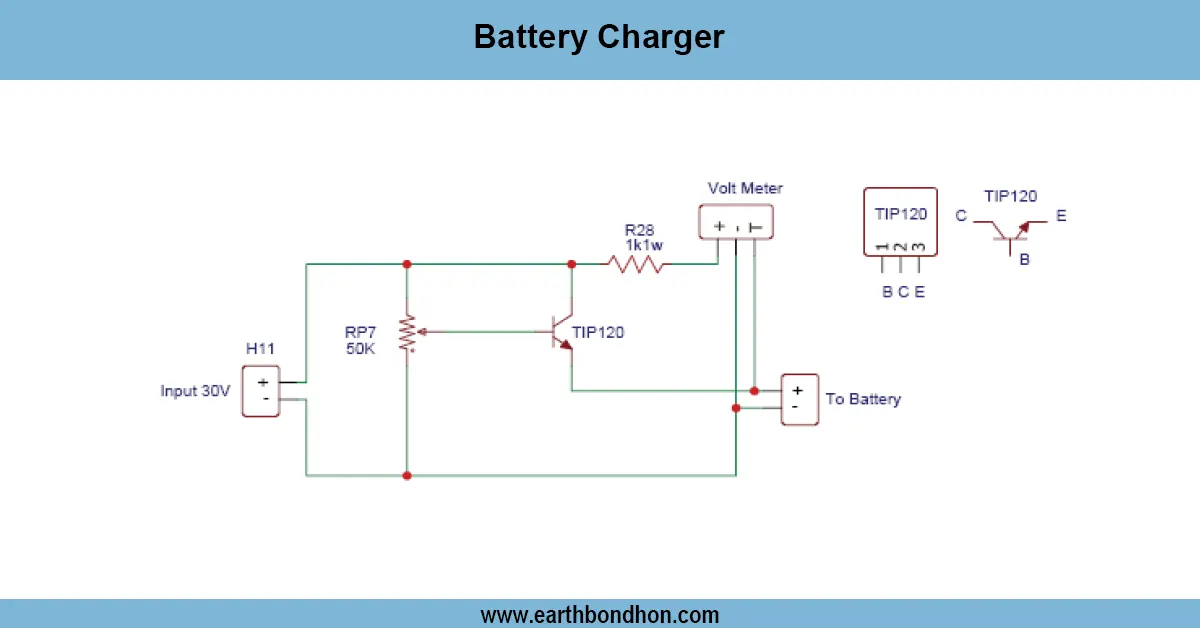
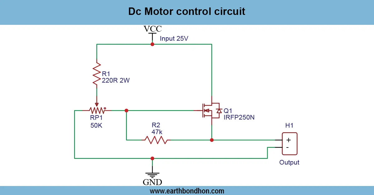
Circuit Diagram Explanation
- Optocoupler LED → Series resistor → Control input
- Phototransistor → Base of driver transistor
- Driver transistor → Transformer primary → VCC
- Emitter → Ground
- Decoupling capacitors across power supply
- Two identical sections for dual transformer outputs
Step-by-Step Construction Guide
- Connect Optocoupler Input: Add resistor in series and ensure correct polarity.
- Driver Transistor Setup: Connect phototransistor to base with bias resistors.
- Transformer Connections: Primary to transistor collector, output isolated.
- Power Supply: 5–12V DC input; high-voltage section for transformer load.
- Testing & Calibration: Test both outputs and adjust bias resistors.
Applications of Optocoupler Transformer Drivers
- Dual-output inverters
- Isolated DC-DC converters
- Industrial automation
- Isolated amplifier circuits
- Multi-output power supplies
Troubleshooting Tips
- No output: Check optocoupler polarity and drive current.
- Transistor overheating: Lower base current, add heatsink.
- Cross-talk: Use separate optocouplers and grounds.
- Weak output: Check transformer primary rating & transistor gain.
- Noise: Add decoupling capacitors.