12 Volt Battery Charger Circuit Auto Cut Off Circuit
Learn how a 12 Volt battery charger circuit with automatic cut-off works. Includes wiring diagram, components, LM317/relay/SCR-based auto cut-off circuits, and FAQs.

An electronic system, a 12 V charger with auto cut-off, is used to charge a battery. The charger is connected until the battery reaches the voltage required to reach full charge, and then the charger turns off automatically. This will avoid excessively charging it and extend battery life.
Preset / potentiometer (10k)
Why Use Auto Cut‑Off in a 12V Charger?
Auto cut‑off prevents battery overcharge, protects against overheating, extends battery life, saves electricity, allows “plug & forget” operation, and improves charging efficiency. It’s essential for UPS, inverter, motorcycle, car, and solar battery systems.
How Auto Cut‑Off Works in a Battery Charger
1. Relay‑Based Auto Cut‑Off Circuit
The simplest and widely used method.
- A preset adjusts the full‑charge threshold (≈14.2–14.4V).
- A transistor senses battery voltage and drives the relay when threshold is reached.
- The relay disconnects the charging supply.
- Advantage: inexpensive and reliable.
2. LM317 Auto Cut‑Off Circuit
Uses LM317 as regulator with a sensing/control stage.
- LM317 provides constant voltage/current and over‑voltage protection.
- Output is set to ~14.2V; a sensing circuit turns off output (via transistor/relay) at full charge.
3. LM358 / LM324 Comparator Auto Cut‑Off
Comparator‑based, more precise option for sealed batteries.
- Battery voltage compared to a stable reference.
- Comparator output goes HIGH at ~14.4V and drives a relay to cut charging.
- Advantages: high accuracy and stability — good for AGM/Gel/SMF.
4. SCR‑Based Auto Cut‑Off Charger
SCR used as a controlled switch for higher‑current systems.
- When full charge is reached the SCR gate is disabled and the SCR turns off.
- Advantages: durable and suitable for high current.
Components Required
- 220V → 15V transformer (5A–10A)
- Bridge rectifier (≥10A)
- 2200µF filter capacitor
- 12V relay
- LM317 or LM358/LM324 (depending on circuit type)
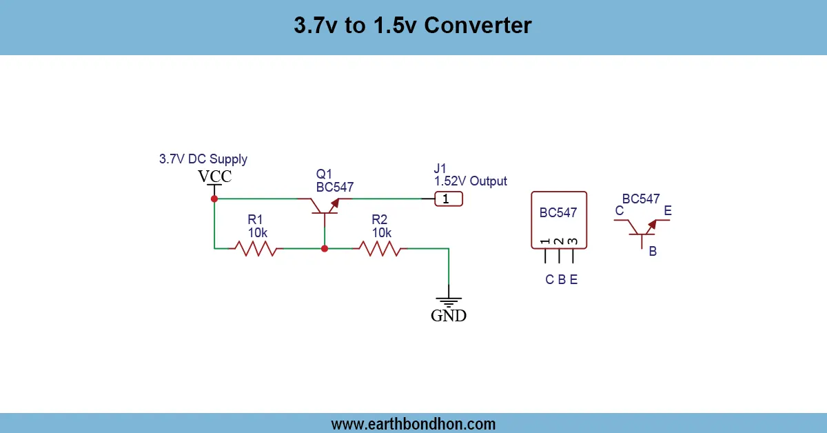
- Transistors (e.g., BC547, BD139)
- 10K potentiometer / preset
- Heat sink, fuse, indicator LED, battery clamps, wiring
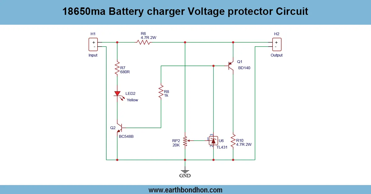
Circuit Diagram Explanation
Mains → transformer → bridge rectifier → filter capacitor gives DC (≈17–21V before regulation). The control circuit (relay, LM317 regulator, comparator or SCR) monitors battery voltage and either opens the relay, reduces regulator output, or disables the SCR when the battery reaches full charge.
Step‑By‑Step Building Instructions
- Build power section: connect transformer → bridge rectifier → filter capacitor.
- Construct the regulation/control section: LM317 regulator or comparator+transistor+relay per chosen design.
- Wire battery terminals (red = +, black = −) and include a suitable fuse.
- Adjust the preset so the relay/comparator activates at ≈14.4V.
- Test with a partially discharged battery and confirm the relay cuts off at the set voltage.
Setting the Cut‑Off Voltage (14.2–14.4V)
Recommended cut‑off ranges by battery type — use a multimeter for precise adjustment:
- Lead‑acid (wet): 14.4V
- AGM: 14.2–14.3V
- Gel: 14.1–14.2V
- SMF: ~14.2V
Charging Current Selection
Use the C/10 rule (battery Ah × 10%). Examples:
- 7Ah → 0.7A
- 35Ah → 3.5A
- 100Ah → 10A
Fast charging up to 20% is possible only with proper protections (auto cut‑off and thermal/current safeguards).
Safety Tips
- Always verify polarity before connecting the battery.
- Ensure good ventilation — batteries can emit hydrogen.
- Use correct fuse and wire gauge for the planned current.
- Keep charger and battery away from heat sources and flammable materials.
- Never touch AC mains connections while powered.
Troubleshooting
| Issue | Cause | Solution |
|---|---|---|
| No cut‑off | Wrong preset setting | Reset preset to 14.2–14.4V |
| Charger overheats | No/insufficient heat sink | Add or improve heat sink |
| Battery charges slowly | Low transformer rating or limiting element | Increase transformer/current capability |
| Overcharging | Relay not opening / faulty control | Replace relay or transistor; check comparator/LM317 circuit |
| Low voltage output | Faulty rectifier or bad connections | Replace rectifier diodes; check wiring |
Applications
- Motorcycle and car battery charging
- UPS and inverter battery maintenance
- Solar charging systems
- Emergency backup batteries and DIY power storage
Conclusion
Auto cut‑off circuits (relay, LM317, comparator, or SCR) make DIY 12V chargers safe and reliable. They prevent overcharge, improve battery life, and allow convenient operation. Choose the method that fits your accuracy, current and reliability requirements, and follow safety best practices when building and testing.