One Motor Control With 2 Meter Connection Wiring
Learn how to wire one motor with two meters using a changeover switch for monitoring, ensuring safe operation and accurate readings from either meter.

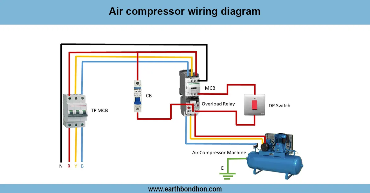
industrial motor wiring diagram
By using a changeover switch to wire one motor with two meters, it is safe to choose which meter to monitor the motor. There is only a meter in operation at any given time, avoiding erroneous readings and back-feed, without affecting the normal operation of the motor.
one motor dual meter connection
A motor with two-meter wiring can be monitored to check the energy consumed or loaded in a given motor using two meters. The primary supply will be connected to a changeover switch such that one can choose either Meter 1 or Meter 2. The output is then connected to the switch input of the motor via an MCB or protective device, which may or may not be provided. Both neutral and earth connections should be correctly fitted in order to be safe. Each meter is switched on at times to avoid back-feed and give the correct readings. Testing entails changing between meters as the operation of the motor is observed and the recording of each meter is checked. Such an arrangement is common in industrial motors, power systems shared, and billing utilities, to give accurate control over motor consumption and to ensure safe operation of an electrical circuit.
Work & Installation (Input → Output Summary)
- ConnectConnect to the changeover switch input.
- Connect outputs of the switch toMeter 1 and Meter 2.
- Connectoutput of the selected meter to the motor supply input.
- IncludeMCB or fuses for protection if required.
- Maintain proper neutral and earth connections.
- Operate the changeover switch to select which meter records the motor load.
Testing & Final Adjustments
- Verify all wiring: main supply, changeover switch, both meters, motor input, neutral, and earth.
- Switch between meters; ensure motor runs continuously.
- Confirm correct readings on each meter when selected.
- Check continuity of neutral and earth connections.
- Ensure MCBs or fuses function correctly under overload conditions.
- Perform multiple switching cycles for reliability.
- Label meters and switch positions for clarity.
- Inspect connections for loose wires or voltage drops.
- Verify that only one meter is active at a time.
- Document wiring diagram and test results for future maintenance.
Frequently Asked Questions - One Motor Control With 2 Meter Connection Wiring:
Why connect a motor to 2 meters?
To monitor energy consumption or load from different sources or for multiple users.
How does the changeover switch work?
It selects which meter is connected to the motor supply at a time.
Is only one meter active at a time?
Yes, to prevent back-feed and ensure accurate readings.
Where is it installed?
Between main supply, meters, and motor input.
Are protective devices needed?
Yes, MCBs or fuses are required for safety.
Is earthing required?
Yes, to ensure safe motor operation.
How to test the wiring?
Switch between meters and verify motor runs normally and meters record correctly.
Can this setup be used for any motor?
Yes, if motor voltage and current match supply and meter ratings.
Does it affect motor operation?
No, motor runs normally regardless of which meter is selected.
Why label meters and switch positions?
To avoid mistakes and ensure correct meter selection.