
Switch board wiring
Learn how to wire a switch with an indicator lamp that stays OFF when the switch is ON, and glows when the switch is OFF for a clear power status.

load switch indicator diagram
In Switch ON Indicator OFF Wiri, ng the indicator lamp is linked in parallel with the switch contacts, across the load, such that when the switch is OFF, the current passes through the load filament to the Neutral and the indicator is on. When the switch is O, N, both halves of the indicator are at the same potential, anit d is turned OFF.
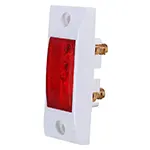
indicator lamp reverse connection
A Switch ON Indicator OFF wiring diagram indicates how to make an indicator lamp a reverse lamp, with a glow only when the Switch is OFF. The system can be handy to determine the unutilized sockets or appliances. The general concept is: the Line (phase) is tied to the switch, and one output is found on the switch connected to the load (bulb/fan), and the other is found on the switch connected to the indicator to the Neutral. But rather than paralleling the indicator with the load, it is paralleled before the switch and after the return of the load. With the switch off, the indicator is powered by the load filament and shines faintly. With the switch ON, the same potential appears on both sides of the indicator, and hence the indicator is not on. This is the type of wiring used in switchboards with neon indicators to indicate the OFF state.
Work / Installation (Inputs → Outputs)
Line (Phase), Neutral, Switch, Load (bulb/fan), Indicator lamp.
Process:
- Connect Line to switch input terminal.
- Switch output → Load (bulb/fan).
- Load → Neutral.
- Indicator one side → Line (before switch).
- Indicator other side → Load output terminal.
- Outputs:
- Switch ON → Load ON, Indicator OFF.
- Switch OFF → Load OFF, Indicator ON.
Testing and Final Adjustments
After wiring, restore power and test. With the switch OFF, the load remains OFF and the indicator glows (it may glow dimly since current passes through the load filament). With the switch ON, the load operates normally and the indicator switches OFF. If the indicator stays ON in both cases, check that it is not connected directly across Line and Neutral. If the indicator never glows, confirm it is connected from Line (before switch) to Load output. For LED loads, some indicators may not glow because LEDs block reverse leakage; use a neon or dedicated pilot lamp for best results. Always ensure proper insulation and wire rating.
Frequently Asked Questions - Switch board wiring:
What is switch ON indicator OFF wiring?
It is a wiring method where the indicator glows only when the switch is OFF.
Why does the indicator glow when the switch is OFF?
Because current flows through the load filament to neutral, lighting the indicator.
Why is the indicator OFF when the switch is ON?
Both indicator terminals get the same potential, so no current flows through it.
Can this be used with LED bulbs?
It may not work properly with LED bulbs because they block leakage current needed for the indicator.
Which indicator is best for this wiring?
A neon indicator lamp is commonly used as it requires very low current.
Is this method safe?
Yes, if properly insulated and connected according to standard wiring rules.
Can I connect the indicator directly across load?
No, that would make the indicator ON when load is ON, not the opposite.
Where is this wiring commonly used?
It is used in switch boards to show OFF condition of appliances like fans or lights.
Why does the indicator glow dimly?
Because it uses leakage current through the load filament when the switch is OFF.
Does this consume extra power?
No significant power is consumed, as neon indicators use only a tiny current.