

Hospital wiring circuit Diagram
Step-by-step wiring guide for hospital electric power switches. Safe input-output connections, MCB/RCCB protection, and cable management for medical facilities.

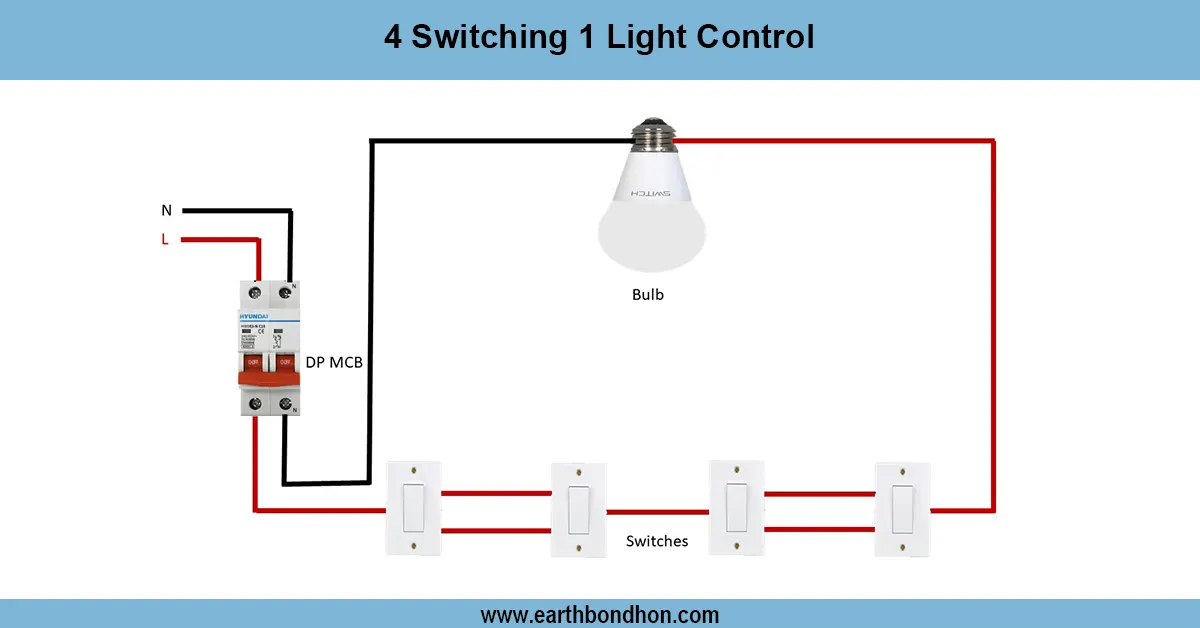
hospital power switch diagram
Hospital power switches are linked to the main supply with MCB/RCCB circuits to medical equipment, emergency lighting, and backup systems to distribute safe electricity.
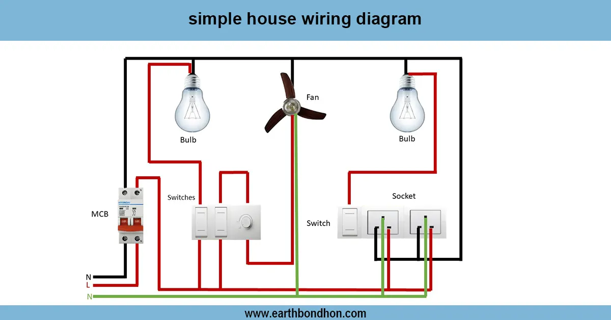
medical facility switchboard wiring
A hospital's electric power switch wiring system provides a reliable, controlled, and safe distribution of electricity
within healthcare setups. Hospitals have various circuits of power supply to enable lighting systems, medical equipment,
emergency equipment, and HVAC, which are not supposed to be turned off.
The primary supply is connected in this type of wiring system to the main switch or the main distribution board. Power is then fed out of there via MCBs, RCCBs, and emergency switches to single hospital circuits. Clearly labeled circuits, cable management, and color-coded wiring make maintenance fast and safe in the event of emergencies.
Backup or emergency power is provided on switches to continue important operations. Installation of cable should be done with the highest standards, with care not to cross-connect with data lines, but with proper phase, neutral, and earth connections.
Such a setup is necessary in hospital wards, operation theatres, ICUs, and labs to secure the patients and sensitive equipment but permit free operation by the staff and maintenance personnel.
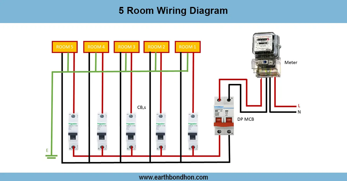
Work / Installation (Inputs → Outputs)
Input: Main supply → Hospital Main Switch → DB/MCC → MCB/RCCB → Hospital Circuits.
- Feed incoming phase and neutral to the hospital main switch or distribution board.
- Connect output to MCBs/RCCBs for individual circuits: lighting, equipment, HVAC, emergency power.
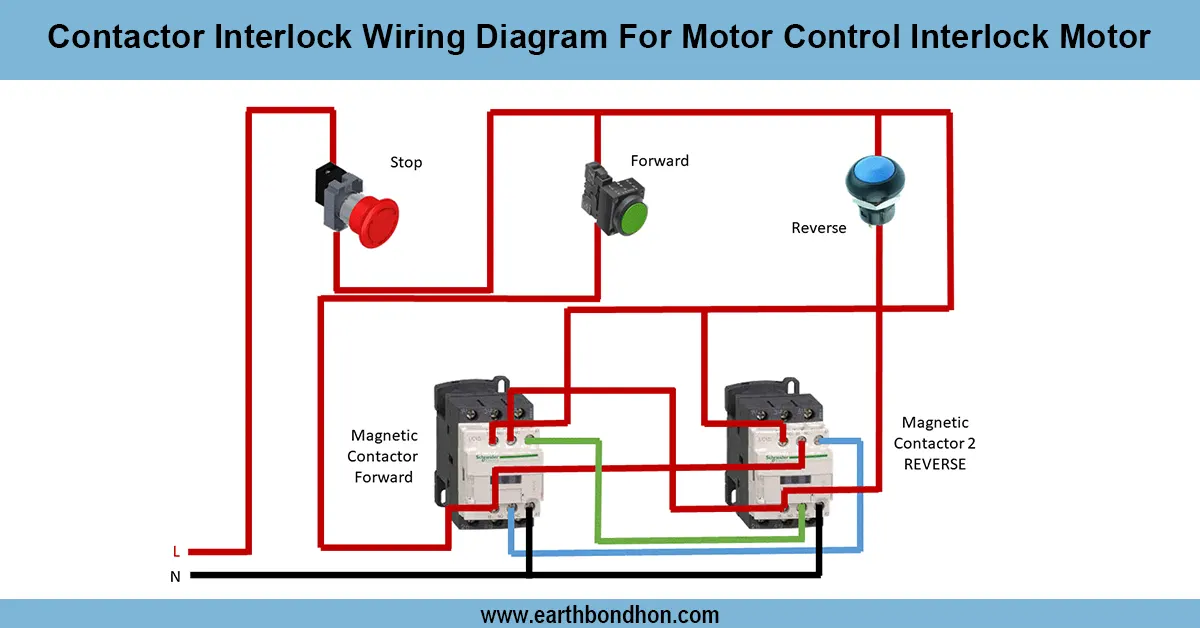
- Install emergency and backup switches in critical areas like ICU, OT, and labs.
- Route cables carefully, separating power and data lines, and follow hospital electrical codes.
- Ensure neutral and earth bars are properly connected, with phase correctly identified.
Output: Each circuit receives controlled, protected power. Emergency switches allow instant cut-off or backup supply to critical systems.
Testing & Final Adjustments
Installation Test Circuit Check voltages at the main switch and test one circuit at a time. Check the operation of MCB/RCCB trips. Make sure that emergency power switches and backup circuits work properly. Test of phase rotation in three-phase construction and correct distribution of loads. Check cable management to avoid accidental shorts and to ensure accessibility. Pre-test vital devices such as ventilators, ICU machines, and other emergency lights to operate continuously.
Designate all switches and circuits to be easily understood by hospital personnel and the maintenance crew. Close all terminals, fix up wiring, and verify earthing. Periodic examination guarantees reliability, patient security, and conformance to hospital electrical guidelines.