
Door Bell wiring Diagram
Learn the basic doorbell wiring diagram, connections, and components for a reliable home doorbell system installation with easy step-by-step guidance.

multiple switch doorbell connection
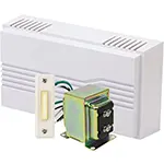
The doorbell wiring circuits explain the most important contacts with the transformer, push-button switch, and bell unit. Pushing the button completes the circuit, which means that the current can flow and causes the ring effect since the current goes out of the transformer to the inside bell. The system is usually driven by a 16-volt AC transformer source delivering low voltage and safe electricity. Connection of the transformer output to the button and bell should be carefully made when wiring, so that once the button is pressed, the circuit closes correctly. This arrangement is mandatory for any mechanical and electronic doorbells in offices and homes.
Formula & Table Summary:
Voltage (V): Usually 16V AC from transformer
Current (I): Depends on bell coil resistance (R) using Ohm’s law:
I = V / R
Power (P): P = V × I
Wiring Connections: Transformer output → Push button → Bell unit
| Component | Voltage (V) | Current (I) | Function |
|---|---|---|---|
| Transformer | 120V AC (input), 16V AC (output) | N/A | Steps down mains voltage to safe level |
| Push Button Switch | 16V AC | Controls circuit connection | Closes circuit to ring bell |
| Bell Unit | 16V AC | Depends on coil resistance | Produces ringing sound |
doorbell circuit wiring
A doorbell wiring scheme illustrates the electrical work and parts required to put in place a standard home doorbell system. Doorbells usually have a push switch, a transformer to reduce voltage, and the actual bell itself. This wiring arrangement typically consists of a low-voltage AC (typically 16V) power supply on the transformer with which to safely operate the bell. The wiring point consists of two or three wires as follows: one wire connects the transformer and the push button, and the second connects the push button and the bell unit, which gets complete when it is pushed. The wiring diagram gives assistance in diagnosing an error, as well as in the performance of a secure installation. In this guide, we will discuss some of the most common types of doorbell wiring, along with mechanical bell and chime units, as well as wireless doorbell systems. The use of good wiring gives an increased life and avoids the risks of electricity.
doorbell wiring
| Input (Switch Pressed) | Output (Bell Rings) | Output (Lamps On) |
|---|---|---|
| Switch 1 | Yes | Yes |
| Switch 2 | Yes | Yes |
| Switch 3 | Yes | Yes |
| No Switch | No | No |
Frequently Asked Questions - Door Bell wiring Diagram:
What voltage is commonly used in doorbell wiring?
Typically, 16 volts AC is used from a step-down transformer for safe operation.
How many wires are needed for a basic doorbell circuit?
Usually two wires connect the transformer, push-button switch, and bell unit.
Can I use a wireless doorbell instead of wired?
Yes, wireless doorbells work without wiring but require batteries and receiver placement.
What happens if I reverse the doorbell wiring?
The bell may not ring or could be damaged; correct polarity is important for some electronic units.
How do I troubleshoot a doorbell that does not ring?
Check the transformer, button contacts, wiring connections, and the bell unit for faults.
Is a transformer required for all doorbell systems?
For wired mechanical or electronic doorbells, a transformer is needed to reduce mains voltage.
Can I use a doorbell with more than one button?
Yes, multiple buttons can be wired in parallel to ring the same bell.
What type of wire gauge is recommended for doorbell wiring?
Typically 18-22 AWG low voltage cable is used for doorbell circuits.
Can a doorbell transformer power multiple bells?
Yes, provided the total current draw does not exceed the transformer rating.
How do I install a doorbell push button?
Mount it near your door, connect wires to terminals, and ensure it completes the circuit when pressed.